1995 Crownline 202BR Restore

Drivewayboater2

Petty Officer 1st Class
Joined
Aug 21, 2019
Messages
385
The csm will actually help keep the resin on the surface and give a better water barrier. Even on the flat part of a sheet, the wood can absorb quite a bit, which will actually reduce the barrier quality. The cut out is pretty much all end grain, which is even worse, so I think the csm would be necessary if you want to use resin there.
Okay see your tinking
 

beta

Seaman Apprentice
Joined
Sep 16, 2023
Messages
30
Thanks for the feedback. I'll pursue the laminated ply.

On the keyhole, the original was gel coated I think. I was thinking about this before and my initial thought was to csm the sides. Seems straightforward.
 

MikeSchinlaub

Chief Petty Officer
Joined
Jan 14, 2025
Messages
530
Thanks for the feedback. I'll pursue the laminated ply.

On the keyhole, the original was gel coated I think. I was thinking about this before and my initial thought was to csm the sides. Seems straightforward.

I don't know how tight the tolerance is for those openings, inboards are removed before we get them. Just keep the extra material in mind for fitment.
 

Pmt133

Lieutenant Junior Grade
Joined
Jan 6, 2022
Messages
1,180
1 layer of csm won't hurt fitment. The steering arm cutout notch may be difficult to glass.

My original cutout was finished with a black oil based paint of some sort. Didn't do anything. Adding glass to resin improves waterproofing by a lot. Wood just sealed with gel or resin really doesn't have much of a water resistance
 

beta

Seaman Apprentice
Joined
Sep 16, 2023
Messages
30
Check my transom thickness this morning after adding 1708 layers yesterday and got 1.975" to 1.985". So added 1 more layer this morning. I'll check it tomorrow but should be good to go.

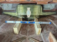
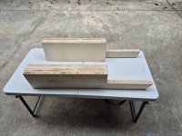
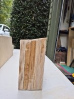
Went with the laminated motor mounts. Cut those and did the lamination yesterday. Today I did some sanding and fine tuning on the mounts. I did many, many, many dry fits to fine tune the profiles. Given the slanted hull under the mounts and the slanted transom, it was a lot of in the boat, out of the boat, repeat, repeat, repeat. I didn't want to have to re-make anything so it was a lot of small changes.
Very pleased with the end result and they sit very level naturally. Spacing and height all look good based on my original mounts. Hopefully I can put CSM on the bottom and get them mounted in the boat with PB during the week. Time to make another wood run for the stringers & bulkheads!
20250928_151841.jpg20250928_151908.jpg20250928_145930.jpg
 

Pmt133

Lieutenant Junior Grade
Joined
Jan 6, 2022
Messages
1,180
When I fitted (is that even a word?) Mine in I took a measurement at all 4 corners for height and set up the table saw angle to cut it. Not perfect but enough that a little PB fixed. Mine were much smaller though and I had a jig to use for the reference as I just made the old ones the year before.
 

beta

Seaman Apprentice
Joined
Sep 16, 2023
Messages
30
I also used a table saw to get the bottom angle. That worked really well once I figured out the appropriate angle.

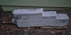
My original mount was overly complex. It had multiple step downs and angled corners that are not necessary. My version was much easier to build and will be easier to glass. Maybe it was designed that way to accommodate different motors but it's not necessary for mine. I like simple!
20250928_191332.jpg
 

beta

Seaman Apprentice
Joined
Sep 16, 2023
Messages
30
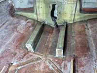
Motor mounts are installed. Covered the bottoms and sides with CSM before installing them. Height and levelness (word?) are dead on so looking good in terms of engine fit. For reference, I ended up using about 20oz of PB for each mount.

20251004_210242.jpg
 

Scott06

Admiral
Joined
Apr 20, 2014
Messages
7,290
I also used a table saw to get the bottom angle. That worked really well once I figured out the appropriate angle.

My original mount was overly complex. It had multiple step downs and angled corners that are not necessary. My version was much easier to build and will be easier to glass. Maybe it was designed that way to accommodate different motors but it's not necessary for mine. I like simple!
View attachment 411980
were the step downs facing the bow or the stern?
 

Scott06

Admiral
Joined
Apr 20, 2014
Messages
7,290
Was thinking maybe they were for access to accessories or starter , which is opposite where the step downs were… if your fuel filter is bottom left as you face the engine might be close ??
 

beta

Seaman Apprentice
Joined
Sep 16, 2023
Messages
30
Was thinking maybe they were for access to accessories or starter , which is opposite where the step downs were… if your fuel filter is bottom left as you face the engine might be close ??
My engine is currently on a stand very similar to the motor mounts and I can't see anything with restricted access. The oil filter in the back and fuel filter is well above the mounts. Both are easily accessible with the motor installed. I guess I'll find out the hard way if I'm not seeing something.
 

beta

Seaman Apprentice
Joined
Sep 16, 2023
Messages
30
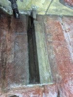
Motor mounts are fully installed and wrapped!

I ended up installing the glass in 6 pieces. Each side is broken into 2 pieces to align with the height step up (4 pieces total). Then there are 2 top pieces for the front and back sections. I did it this way to simplify the cloth cutouts and the application. Trying to do a single piece that goes across both sides and the top would have been really tough. In retrospect, I could have done the outside in 1 piece since the vertical surfaces are aligned. I used 3 batches of ~32oz of resin for each mount. Breaking it up keep the resin fresh without have to rush.

20251029_181208.jpg

1761851205332.jpeg
 

beta

Seaman Apprentice
Joined
Sep 16, 2023
Messages
30
I'm going to cut out the stringers and bulkheads this weekend. I'm planning to use foam board to dial in the exact shapes then transfer the shape to the plywood. This is what I did for the transom. Any suggestions/techniques on this would be appreciated.
 
Top