1978 Islander 22 I/O

66Holiday924

Chief Petty Officer
Joined
Aug 21, 2017
Messages
597
I took apart the windows. The side windows aren't cracked or broken or anything, the front cabin window is though, and the plan is to have it remade, and I want all of the windows to match so I'm going to have them all rebuilt. I'm leaning toward a dark tint plexiglass, something that makes it hard to see what's inside.

So, now to get the windows off to the plexiglass shop, and clean the frames up.
 

Attachments

  • 20250128_184352416_iOS.jpg
    7.6 MB · Views: 11

66Holiday924

Chief Petty Officer
Joined
Aug 21, 2017
Messages
597
I've been getting some work done on the Islander and I'm about a month behind on my updates. My work has been kind of spread, so I'm going to update it with each individual component that I've worked on so it's easier to follow.

The first thing I worked on was getting the fuel tank installed. I ordered the tank custom from RDS and had a really good experience. They worked with me until it was exactly what I wanted and took the time to learn about my project and offered some pointers. It's one of those things though, you're basically biting your nails until it is in place, and you can see it's going to work.

I laid the tank into position, between the port and starboard stringers. Then on the ends (fore & aft), I cleaned, slightly modified and reinstalled the bulkheads to complete the rectangle and encase the tank. As recommended by RDS, I used 3/8 nitrile rubber strips as a buffer between the bottom of the tank and the ribs, and on the ends, leaving a little bit of room for expansion. The strips were applied with 5200. I buttered them, stuck them in place, ensuring that there was no way for water to get between the rubber and the tank, and then let them cure for a few days before the install.

The aft bulkhead, from Starcraft, was designed with a nice little one inch opening hole. It looks nice but in my opinion is a design flaw. That opening could easily become obstructed and the bulkhead would then help to trap water in the bilge. So, I opened it up. I'm kind of obsessed with water management in the bilge and working to keep it dry. I like any water in the bilge to be able to flow easily to the bilge pump, and I like the bilge to be able to dry while the boat is not in use.

I had more pictures, but they are too large to post...
 

Attachments

  • 20250917_204206710_iOS.jpg
    3.7 MB · Views: 8
  • 20250917_204216857_iOS.jpg
    1.8 MB · Views: 6
  • 20250925_162127902_iOS.jpg
    3.5 MB · Views: 6
  • 20250925_162133476_iOS.jpg
    3.7 MB · Views: 6
  • 20250925_162151197_iOS.jpg
    3.6 MB · Views: 6
  • 20250925_175356419_iOS.jpg
    3 MB · Views: 7

66Holiday924

Chief Petty Officer
Joined
Aug 21, 2017
Messages
597
I decided that I want the weight of the batteries to help balance out the boat and as of now I'm planning on four batteries, two for the boat, two for downriggers & other accessories. I think having that weight up front behind the cabin will help give the boat a better ride.

My plan is for the batteries to rest behind the cabin and to recess them into the floor as much as possible, so I don't have a 10" box sticking up. So, where the rest of my decking is going to be framed up 2", the area of the batteries will not be. Instead, the batteries will rest on 1/4" aluminum plating. So, I installed my plating with the closed cell insulation foam under for floatation.
 

Attachments

  • 20250919_150203545_iOS.jpg
    2.8 MB · Views: 5
  • 20250919_150411098_iOS.jpg
    3.5 MB · Views: 5
  • 20250919_151030350_iOS.jpg
    2.9 MB · Views: 5
  • 20250919_145509127_iOS.jpg
    20250919_145509127_iOS.jpg
    2.7 MB · Views: 5

66Holiday924

Chief Petty Officer
Joined
Aug 21, 2017
Messages
597
The cabin framing wood all seemed solid except the front piece, directly under the front cabin window. So, I rebuilt that with a piece of mahogany, treated it with my Old Timer's Formula (OTF) and reinstalled it.

After the mahogany was installed, I cleaned up the aluminum trim piece that runs across the top and reinstalled it using a dab of 5200 on the screws, so in the future if the window leaks, in addition to the OTF, there will be protection at the screws.

The rest of the framing was solid (appears to be oak). I went screw to screw and torqued it all back down.
 

Attachments

  • 20250919_160542546_iOS.jpg
    20250919_160542546_iOS.jpg
    2.8 MB · Views: 6
  • 20250919_160853849_iOS.jpg
    20250919_160853849_iOS.jpg
    2.7 MB · Views: 6
  • 20250920_181709872_iOS.jpg
    20250920_181709872_iOS.jpg
    2.4 MB · Views: 6
  • 20250925_191516531_iOS.jpg
    20250925_191516531_iOS.jpg
    2.6 MB · Views: 6

66Holiday924

Chief Petty Officer
Joined
Aug 21, 2017
Messages
597
Next, I installed my natural ventilation and aluminum floor framing.

Natural ventilation is mandated by the coast guard. I believe this boat was built before the mandate, so it is technically grandfathered in, and doesn't have to have it, but I'm doing this, and I believe in the purpose it serves, so I installed it.

For the natural ventilation I installed louvers and collection boxes, both port and starboard. Each collection box has two bilge blower hoses. They both ventilate the fuel tank compartment and the engine compartment.

The aluminum framing I used is 2x3 inch. The pictures say it all. I used high strength, all aluminum, structural blind rivets to install the framing. The 2" rise will give the fuel tank fittings (fill, vent, etc.) the clearance it needs.
 

Attachments

  • 20250919_145340469_iOS.jpg
    2 MB · Views: 4
  • 20250919_145450121_iOS.jpg
    20250919_145450121_iOS.jpg
    1.7 MB · Views: 6
  • 20251001_180036985_iOS.jpg
    2.7 MB · Views: 5
  • 20251001_180042457_iOS.jpg
    2.9 MB · Views: 4
  • 20250927_192839461_iOS.jpg
    3 MB · Views: 4
  • 20251001_175958765_iOS.jpg
    3.2 MB · Views: 4
  • 20251001_180119142_iOS.jpg
    1.9 MB · Views: 7

66Holiday924

Chief Petty Officer
Joined
Aug 21, 2017
Messages
597
I decided early on that this boat will accommodate those who sit while they pee. It might seem like I'm getting ahead of myself, but I think it's important to incorporate this into the design of the substructure. If I build it with this in mind, I can do a lot better job on the install.

The Port-a-Potty sits on a piece of sheet aluminum I installed last year, and it fastens down with Thetford's tie down kit. A piece of Coosa acts as a buffer between the toilet and the aluminum plating and the tie-down kit gets fastened through the Coosa and plating with through bolts. I built the Coosa piece out of plywood first to make sure it would work, before mutilating any Coosa (stuff is expensive).

I will need to install two access plates later, one, to allow the toilet to be flushed, and the other, gets installed later, when I build the floor, and it allows access to the nuts on the other end of the through bolts that secure the tie-down.
 

Attachments

  • 20241125_173824898_iOS.jpg
    20241125_173824898_iOS.jpg
    1.7 MB · Views: 5
  • 20250926_144354085_iOS.jpg
    3.4 MB · Views: 2
  • 20250926_144949930_iOS.jpg
    3.8 MB · Views: 3
  • 20250926_145826505_iOS.jpg
    3.2 MB · Views: 3
  • 20250926_180228056_iOS.jpg
    3.8 MB · Views: 3
  • 20250926_181309160_iOS.jpg
    3.8 MB · Views: 3
  • 20250926_181812938_iOS.jpg
    20250926_181812938_iOS.jpg
    1.7 MB · Views: 5

66Holiday924

Chief Petty Officer
Joined
Aug 21, 2017
Messages
597
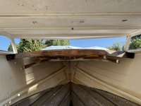
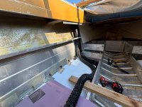
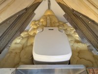
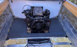
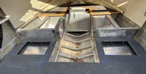
I used Total Boat's pour-in expanding floatation foam around the port-a-potty to give it some sturdiness.

Floatation foam is very strong, structural material. It helps support decking. So, with that in mind, my idea was to get it installed around the base of the port-a-potty. My idea was that when it expands, it will conform to the contours of the potty giving it a "seat" specific to both the potty and my set-up. It'll conform to both the potty and my boat specifically, giving it a seat unique to this install, and it alone would be enough to secure the potty, without the tie-down kit.

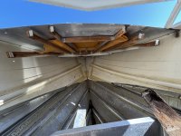
The problems I had to be aware of:

- The handle to release the tie-down has to be accessible.
- The handle to flush has to be accessible.
- The toilet flares out and then in, so the flares have to be minded so the foam doesn't lock the toilet down.
- I didn't know whether or not the foam would stick to the toilet, so that had to be dealt with.

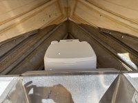
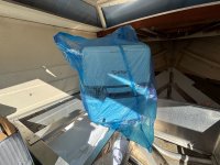
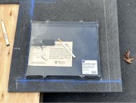
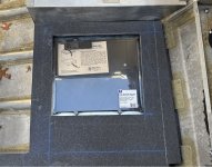
This is going to be pictures say 1000 words, but here goes my explanation. My solution to the presented problems was to mutilate the box, that the potty came in, so it could be taped to the upper half of the toilet minding the upper flare and allow the backend of the box to come down leaving space for rear tie-down access. Then the entire potty was placed into a garbage bag and the box taped to it. So, it kind of looked like the potty was wearing a helmet or had a mullet. The garbage bag allowed a barrier between the foam and the potty, so the foam could form to the potty but not risk it sticking to it. The last problem was leaving access for the flush handle. This was done by carefully pouring the foam in that area.

This is all what I meant in my last post when I said, knowing the boat will have it, means I can do a better job installing it now, because my install idea effects floatation foam.

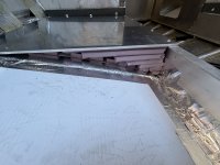
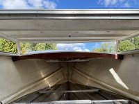
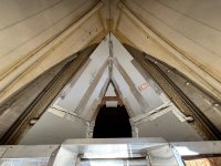
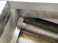
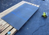
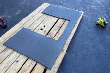
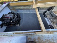
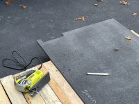
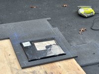
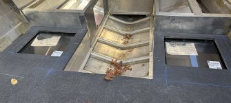
You can see my sheet vinyl in the first picture. I use that to span the ribs, so that when the foam is installed there is a cavity between the foam and the hull where any water can flow down and back to the bilge pump freely. This keeps water from being trapped between the foam and the hull and I really believe it extends the life of the hull and the foam dramatically.
 

Attachments

  • 20250929_180810795_iOS.jpg
    20250929_180810795_iOS.jpg
    1.6 MB · Views: 4
  • 20250929_181100212_iOS.jpg
    20250929_181100212_iOS.jpg
    1.5 MB · Views: 4
  • 20250929_181148819_iOS.jpg
    20250929_181148819_iOS.jpg
    1.5 MB · Views: 5
  • 20250929_182549961_iOS.jpg
    3.2 MB · Views: 2
  • 20250929_205932289_iOS.jpg
    3.7 MB · Views: 3
  • 20250930_122814029_iOS.jpg
    2.9 MB · Views: 3
  • 20250930_122844426_iOS.jpg
    2.8 MB · Views: 3
  • 20250930_131033043_iOS.jpg
    20250930_131033043_iOS.jpg
    1.3 MB · Views: 5

66Holiday924

Chief Petty Officer
Joined
Aug 21, 2017
Messages
597
After I installed the floatation foam around the port-a-potty I installed it down the port & starboard sides. I left the aft for later because I still have work back there. I'm using Total Boat's 2-Gallon kits. Each kit is supposed to float 300lbs and so far, with more to go yet, I've used 1.75 kits. In addition to the kits, I stuffed some of the purple insulation board that everybody uses for flotation where I didn't want to pour in the foam, and I've been hacking up chunks of the original boat flotation Styrofoam and using it with the expanding foam, because both, I think it's cool to reuse it, and it saves on cost to do so.

As I've been explaining in prior posts, last year, I installed sheet vinyl that bridges the ribs of the boat creating a cavity under the foam. The open cavity allows any water that gets into the boat to flow freely down to the bilge, and to the bilge pump. This helps the issue of water being trapped between the hull and the foam. I used "Buck" brand HVAC Tape to install the sheet vinyl, and I have to say, I am very impressed with it. It's quickly becoming my best friend on this build. It seems like that tape comes in handy a lot. It will stick to anything, and it doesn't let go. It sticks through the extremes of winter and summer. I use the tape to fasten down the sheet vinyl and manage the foam, keep it from spilling into areas I don't want it.

With the fuel tank being in the adjacent compartment to the compartments, I installed the foam, I was worried foam would creep into it, which usually happens a little. Nothing. None at all. I squeezed my face to the bottom of the bilge to look and saw daylight down through the entire fuel tank compartment.

You can see in the pictures, I poured the foam right onto my natural ventilation hoses. This will protect and secure them.
 

Attachments

  • 20250929_192914611_iOS.jpg
    20250929_192914611_iOS.jpg
    2.5 MB · Views: 5
  • 20250927_192906541_iOS.jpg
    3.1 MB · Views: 3
  • 20251002_181002997_iOS.jpg
    20251002_181002997_iOS.jpg
    1.4 MB · Views: 5
  • 20251002_183430752_iOS.jpg
    2.9 MB · Views: 5
  • 20251002_200117727_iOS.jpg
    3.1 MB · Views: 3
  • 20251004_155227187_iOS.jpg
    3.2 MB · Views: 4
  • 20251004_155232434_iOS.jpg
    3.1 MB · Views: 3
Last edited:

66Holiday924

Chief Petty Officer
Joined
Aug 21, 2017
Messages
597
Still getting caught up on the work that I've been doing...

You may have seen in some of the recent pictures, I installed a highspeed water intake. I want the boat to have a washdown system. It turns out that if you want to be able to use it while the boat is in motion, you need one of these. Mine is Groco brand, which seems to be the leading brand. I had to cut a little bit of threading off, so the valve could tightly screw down. I wasn't too thrilled about using brass against the aluminum, but this is going to be strictly a freshwater boat, and there is a healthy layer of 5200 between the two metals. The white piece in the pictures is a "backer" that Groco sells. It basically distributes the pressure put on the valve to a wider area making damage to the valve or hull way less likely.

I put it on the port side with the scoop opening facing forward, so it can "scoop" water. I chose the port because I plan on putting transducers on the starboard side. I'm hoping that my deck access plate for the fuel tank will work to provide access to this too.

These pictures are from the dry install, don't have any of the permanent install... The only difference is that I sanded away the paint in the area, used black 5200 to seal it, and 316 stainless screws. I used black 5200 because I plan on painting the bottom with black antifouling paint someday.

I was a little wary about sanding away the paint, right up until I did it. It came off way to easy, had I sealed it to that, it wouldn't have been sealed very good.
 

Attachments

  • 20250928_140341493_iOS.jpg
    3.9 MB · Views: 4
  • 20250928_140519702_iOS.jpg
    2.7 MB · Views: 4
  • 20250928_143141852_iOS.jpg
    20250928_143141852_iOS.jpg
    1.1 MB · Views: 5
  • 20250928_143207618_iOS.jpg
    20250928_143207618_iOS.jpg
    818.8 KB · Views: 5
  • 20250928_143239203_iOS.jpg
    1.8 MB · Views: 4

66Holiday924

Chief Petty Officer
Joined
Aug 21, 2017
Messages
597
After the framing was in, I used some angle, and leftover neoprene rubber strips I had, to make some top padding for the fuel tank. I buttered one leg of the angle with 5200, stuck the padding to it, and riveted the other leg to the aluminum framing. I left a little room, about 1/4", as recommended by RDS, to allow for the tank to expand.

NOTE: Certain rubbers react with aluminum to cause galvanic corrosion. The Rubber I used for all of my padding is neoprene rubber, which is safe to use, and recommended to by the fuel tank fabricator. I mistakenly said nitrile in past posts, but it's neoprene rubber.
 

Attachments

  • 20251014_202006159_iOS.jpg
    2.4 MB · Views: 8
  • 20251014_202009907_iOS.jpg
    2.9 MB · Views: 5
  • 20251014_211358625_iOS.jpg
    2.4 MB · Views: 5

66Holiday924

Chief Petty Officer
Joined
Aug 21, 2017
Messages
597
Installing the bulkhead around the step-down to the cabin.

I saw an opportunity to cram some more floatation foam in, so I took it.
 

Attachments

  • 20251018_160013410_iOS.jpg
    2.8 MB · Views: 5
  • 20251018_160018957_iOS.jpg
    20251018_160018957_iOS.jpg
    1,007.5 KB · Views: 4
  • 20251018_160031692_iOS.jpg
    20251018_160031692_iOS.jpg
    1.5 MB · Views: 4
  • 20251018_160301711_iOS.jpg
    2.7 MB · Views: 5
  • 20251018_160942768_iOS.jpg
    3 MB · Views: 5
  • 20251018_161342788_iOS.jpg
    2.6 MB · Views: 5
  • 20251018_162051251_iOS.jpg
    2.5 MB · Views: 5

SHSU

Lieutenant Junior+Starmada Splash Of The Year 2019
Joined
Mar 8, 2017
Messages
1,760
Very nice. Can't have enough foam. Something you want but hope you never need.

SHSU
 

66Holiday924

Chief Petty Officer
Joined
Aug 21, 2017
Messages
597
Dry fitting two sections of decking. I'm using coosa for the deck. This will mean that there is nothing that can rot to this point... My framing is aluminum, there's the vinyl sheeting I used to bridge the ribs, and floatation foam. I suppose someday the floatation foam could become waterlogged...

The transom and the entire floor structure of this boat are coosa, won't rot.

I want to get the decking dry fitted before the winter because I need it in place to make an engine cover and I've decided that since the boat is essentially, as resistant to rot as it gets, I'm good with using a big-box store cover for the winter, as long as there is an engine cover, in case the cover fails.

I'm not ready to permanently install the decking. I still have work to do on the engine stringers, framing and rear floatation foam.
 

Attachments

  • 20251020_192232846_iOS.jpg
    20251020_192232846_iOS.jpg
    3.7 MB · Views: 2
  • 20251020_193116620_iOS.jpg
    20251020_193116620_iOS.jpg
    2.6 MB · Views: 3
  • 20251020_193410352_iOS.jpg
    20251020_193410352_iOS.jpg
    2.5 MB · Views: 3
  • 20251023_160036364_iOS.jpg
    20251023_160036364_iOS.jpg
    3.3 MB · Views: 3
  • 20251023_160045931_iOS.jpg
    2.4 MB · Views: 3
Top