2002 4.3 GXI-B Audible Alarm & Protection Mode

Status
Not open for further replies.

jake7995

Cadet
Joined
Mar 28, 2012
Messages
23
Another issue I found is that if I pressure up the fuel system and turn off the key the system will lose pressure. Is the check valve in the fuel cell that is supposed to prevent fuel from flowing back out of the fuel rail causing the pressure to drop. Thanks in advance for any help!
 

DouglasW

Petty Officer 1st Class
Joined
Apr 20, 2018
Messages
269
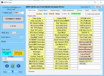
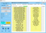
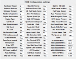
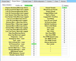
DTC81 has so many possibilities that it is almost useless as such. You need a scan tool to see the readings from each sensor. In general, you can see what data is available from the ECM by using my free scan app. Just open it and see the data shown on each tab. I capture all the data available from the MEFI-4 ECM. I don't think the exhaust temp is one of those available though.
 

DouglasW

Petty Officer 1st Class
Joined
Apr 20, 2018
Messages
269
[No message]
 

Attachments

  • photo302041.png
    photo302041.png
    113.3 KB · Views: 1
  • photo302042.png
    photo302042.png
    103.7 KB · Views: 1

muc

"Retired" Association of Marine Technicians...
Joined
Jul 7, 2004
Messages
2,246
Another issue I found is that if I pressure up the fuel system and turn off the key the system will lose pressure. Is the check valve in the fuel cell that is supposed to prevent fuel from flowing back out of the fuel rail causing the pressure to drop. Thanks in advance for any help!

3. A fuel system that drops more than 14 kPa (2 psi)
in 10 minutes has a leak in one or more of the
following areas:
• The fuel pump check valve.
• The fuel pump flex pipe.
• The valve or valve seat within the fuel pressure
regulator.
• The fuel injector(s).
4. A fuel system that drops more than 14 kPa (2 psi)
in 10 minutes after being relieved to 69 kPa (10
psi) indicates a leaking fuel pump check valve.
5. Fuel pressure that drops off during acceleration,
cruise or hard cornering may cause a lean
condition. A lean condition can cause a loss of
power, surging or misfire.
 

muc

"Retired" Association of Marine Technicians...
Joined
Jul 7, 2004
Messages
2,246
I don't think the exhaust temp is one of those available though.

I think exhaust over temp, low oil press and coolant over temp are all shown as general warning one.
 

jake7995

Cadet
Joined
Mar 28, 2012
Messages
23
Douglas, what type of cable do I need to use your scan system and where do I get it? I did have the system scanned as I showed in an earlier post but the codes didnt line up with the symptoms. I would like to see live data coming into the ECM if I can plug into it and use your software.

Muc, I have the fuel cell apart but I'm not sure which component is the check valve. Finding the spot where it's leaking might be complicated.
 

muc

"Retired" Association of Marine Technicians...
Joined
Jul 7, 2004
Messages
2,246
The check valves are in the pumps.
 

DouglasW

Petty Officer 1st Class
Joined
Apr 20, 2018
Messages
269
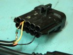
To buy a ready-made cable would cost at least $200 as part of a scan kit from OBD Diagnostics:
https://obd2allinone.com/mefiscan.asp
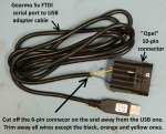
But the software you get with that is not very good. Mine is better. I can tell you how to make a cable for about $30 or less. To start, you need a cable like this (p.s. don't bother with the cheaper knockoffs that sell for under $10. Most of them do not work with the latest drivers from FTDI):
https://www.amazon.com/Gearmo-Header...i+cable+gearmo

Also, buy a connector and pins for the 10-pin "Opel" style connector from Mouser Electronics
pins, 2 minimum but at least 4 or 5 for spares: https://www.mouser.com/ProductDetail/829-12045773
connector body: https://www.mouser.com/ProductDetail/829-12045808

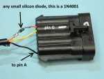
And one general purpose silicon diode (buy 2 or 3 at least): https://www.mouser.com/ProductDetail...Y4ltlfP1xumf9h

If you want to go that route, let me know and I will post the instructions. To do it right, you will need some basic soldering ability.
 

DouglasW

Petty Officer 1st Class
Joined
Apr 20, 2018
Messages
269
[No message]
 

Attachments

  • photo302173.jpg
    photo302173.jpg
    71.2 KB · Views: 1
  • photo302174.jpg
    photo302174.jpg
    59.2 KB · Views: 1

jake7995

Cadet
Joined
Mar 28, 2012
Messages
23
Muc, would you check the pump check valves by trying to blow air through them backwards?

Douglas, I am going to order the parts to bulk the connector. Is installing and using the software self explanatory? Does it show codes and can it control anything on the boat?
 

DouglasW

Petty Officer 1st Class
Joined
Apr 20, 2018
Messages
269
Also Douglas, do you have a sketch of the exact pin locations that the wires go to?

The connector is marked with the pin letters. They are a bit hard to see, but they are there.

There is no real installation procedure. You just unzip the file and place it in a folder of your choice. Ignore any warnings about running it because it is not digitally signed because that costs a bunch of $$$. The cable drivers should self install if the pc has connection to the web. It will show any trouble codes and a lot of other information. but it will not control anything on the engine.
 
Last edited:

muc

"Retired" Association of Marine Technicians...
Joined
Jul 7, 2004
Messages
2,246
Muc, would you check the pump check valves by trying to blow air through them backwards?

I would test the valves using the procedure posted above.


I have always worked for a Volvo dealer since this fuel cell came out. So I have never attempted a repair, but if it was my boat. I would try lightly blowing air both ways as well as flushing with clean solvent both ways. I have always felt that this pump should be serviceable. But as a Volvo certified tech, I have to follow their guidelines in the shop.
 

jake7995

Cadet
Joined
Mar 28, 2012
Messages
23
I ordered all the parts today to make the cable. I was confused because 2 wires go to the same pin. I got it now...Looks pretty simple. Thank you very much for this info and software!

Muc I will continue with the tests on the pumps and reassemble the fuel cell. Unfortunately I won't be able to test the boat until next spring. We had our first snowfall last night...ran out of time. I will update this forum with my results for anybody else's reference.
 

jake7995

Cadet
Joined
Mar 28, 2012
Messages
23
DouglasW, thank you very much for the program and information to build the cable. It worked perfectly, and I was able to pull some information.

To recap what I'v done. I have tested resistance and voltage at all injectors. Everything tested good. I have flow balance tested all injectors, and they were all within 1 psig. I pulled the fuel cell part and found some paint flakes in the suction screen of the low pressure pump. I cleaned that and reassembled it.

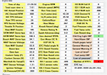
This last weekend I hooked up the scan tool and pulled the attached information. One thing I noticed is that when I cleared the codes, they immediately came back. All 4 codes are attached. I am thinking there is an ECM issue, and it's not processing the voltages correctly. I am thinking I should send the ECM off and have it tested for $80. Since the datastream doesn't show injector voltage, I don't have any way to tell if the ECM is reading voltage correctly. Am I thinking logically? Is it worth spending the money to have it tested?

Thanks,
Jake
 

Attachments

  • photo303000.png
    photo303000.png
    33 KB · Views: 0
  • photo303001.png
    photo303001.png
    229.5 KB · Views: 0
  • photo303002.png
    photo303002.png
    243.5 KB · Views: 0
  • photo303003.png
    photo303003.png
    272.6 KB · Views: 0

DouglasW

Petty Officer 1st Class
Joined
Apr 20, 2018
Messages
269
While it's possible, I kind of doubt the ECM is in error. It uses the same measurement system for all the other measurements, which look ok.
How did you determine that the resistance and voltages are correct for the injectors?

Since you have no history on the engine, perhaps the wrong injectors were installed at some time?
 

jake7995

Cadet
Joined
Mar 28, 2012
Messages
23
I resistance tested each injector with a DMM as shown in the manual. I also went a step further and tested the tested the coils voltage with a Kent Moore injector tester. Everything was within spec. Then I probed the injector wire right at the ECM and wathe the resistance as I hooked up each injector individually to make sure the ecm was getting the same signal that I measured at each injector. anything is possible, but if the resistance is correct on the injectors the voltage should be right?
 
Status
Not open for further replies.
Top