2003 Volvo SX spline, bearing, u-joint inspection advice needed

pgwin

Cadet
Joined
May 31, 2015
Messages
9
image_221934.jpg image_221939.jpg image_221935.jpg image_221938.jpg image_221937.jpg Hi - I could sure use some advice tips on this inspection please.

First the boat history.
I purchased it from the original owner last year, Four Winns 4.3GL/Volvo SX with 125hrs and always garaged and fresh water only. I used it all last year - the outdrive was always very quiet when it was cold and after warming up at idle an not in gear a bit of noise could be heard. I had researched this in depth and found it was not uncommon with the SX drive.

The last trip of the year i made a grave mistake and accidently had bumped into the trim button not realizing it and then hammered the throttle pulling a skier out with the drive up to some degree - not sure how much but the bow the boat came up abnormally high. I know that's the fatal sin for a boat driver due to stress due to the u-joint angles.

After that i thought i could hear noise in the drive when at speed say 2500 rpm where i had not noticed it before (suspect u-joint, gimbal bearing, coupler?) but perhaps it was a paranoid worried conscience about the previous event!!!! When winterizing end of season last year the drive was silent at startup then after warming up 10 minutes with water running through, it sounded like when we first bought it - the subtle noise after warm up.

But this demands an inspection to see the real state of affairs. Oh the PO only had a service at 50 hours, but since that he did not pull the drive to grease the splines.

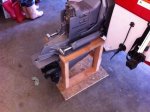
So I've pulled the drive:
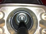
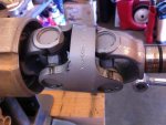
1. U-joints - feel smooth as silk, can detect any looseness in them but that is hand torque loading.
2. Gimbal bearing feels butter smooth, no noise, no looseness detected
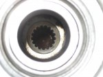
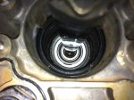
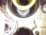
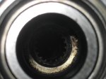
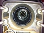
3. Splines: are dry grease on the input shaft, some mushy grease on the internal splines of the engine coupler and the teeth look "pointed" but it is not easy to see. So the question here is are they worn due to not greasing? and need replacement?

The last 2 pics show the internal spline, which to me look well rounded, the input shaft shows no wear! Is the internal spline very soft steel?

I could use some pointers in any specific methods to inspect and or service while i'm in here.

thx,

Paul
 
Last edited:

dypcdiver

Lieutenant Junior Grade
Joined
Nov 1, 2005
Messages
1,043
I see your problem, only solution is to pull the motor and replace the coupler. If there is no wear on the drive shaft then I would suspect the coupler splines have not been heat treated correctly.
When I run an alignment check on mine the peaks or the splines leave a mark approx. 1/16" wide. You may also have an alignment problem.

The grease that should have been used is a moly based which should have retained its lubricating properties even when quite dry, 125 hours is not a lot, some boats do more than that in a season. Hence the reason I suspect a fault with the coupler.
 

pgwin

Cadet
Joined
May 31, 2015
Messages
9
image_221978.jpg After a very involved clean up of the coupler i think the splines are in better shape than initially thought. Seems the grease stains make the grooves look rounded out but in actuality they are not - sure would be nice to have a boroscope for this!

So that said i may just grease the gimbal (one i remedy the four wins - requiring a stub right angle zerk connector), apply Moly 60 paste the coupler and input shaft and put it back to together.

Oh i will get an alignment shaft to check centeredness of the gimbal bearing to coupler - need to get one on order.
 
Last edited:
Tail_Gunner

Admiral
Joined
Jan 13, 2006
Messages
6,237
Well i cant see anything wrong with those splines, doing what you did would be hard on the knuckles or ujoints but on the spline's???? dont think so. I dont how much better that could look.
fetch
 
Last edited:

dypcdiver

Lieutenant Junior Grade
Joined
Nov 1, 2005
Messages
1,043
Looks much better cleaned up, but I still think the voids look wider than normal. Well worth checking the alignment then grease it up and go boating with your fingers crossed.
 

pgwin

Cadet
Joined
May 31, 2015
Messages
9
Got the alignment tool, and no go - so alignment off - as suspect. I found a "imprecise" pipe at about 0.990 diameter to put into the coupler with the idea that allowing this to center within the coupler it will indicate the direction of misalignment. The pipe is a snug fit (no wobble) and I have rotated it 90 degrees in the coupler all the way around with no real change of radial position in the gimbal bearing (so it serves as a good rough indication).

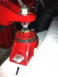
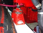
The first picture is unadjusted motor mounts. There is about 1/16" gap at the top and about .300" at the bottom. This would seem to me very out of alignment.
IMG_7786-50.jpg IMG_7787-50.jpg


This is the alignment after 3 turns of each of the front motor mounts to raise the front of the motor (moving the correct direction but not cigar).

It looks like I many need to go 6 turns. I did not expect the alignment tool to fit, and it didn't. Maybe for a boat 12 yrs old the rubber motor mounts have compressed. Is there also a rear motor mount -i didn't see one - does it pivot or will it sag.

I really don't know what to think about the amount i am having to move the motor - does this sound expected - thoughts?

It likely is now time to go get a 1" cold rolled steel round and turn down the front to make a precision indicator. It seams this would be a good way to align by using a shim gage to check for centering of the shaft in the gimbal bearing. I will be replacing the bearing but want to get this aligned first (see that it can be) and then replace bearing and recheck / adjust as necessary.

Thx,

Paul

IMG_7798-4turn-50.jpg IMG_7799-4turn-50.jpg
 

pgwin

Cadet
Joined
May 31, 2015
Messages
9
Engine mount bottom nuts are now each rotated 6 turns to raise the front of the engine (6/18 =.33 inch). However still not aligned visually in the gimball bearing. I did swivel the bearing and refind the coupler with the alignment shaft.

Seams the effect of alignment is dropping off with each turn of the mount nuts. No chance of starting the alignment tool in the coupler.

Any suggestions? I hate to keep moving the engine - given this seems a long way out? I have about 1 nut of thread more i could go maximum.
 

Tail_Gunner

Admiral
Joined
Jan 13, 2006
Messages
6,237
Did you ever just insert the bar and read the witness marks or did it catch badly on insertion??? Your motor mounts are bedded in stringer's are the stringer's wet they can be core sampled as simply as drilling them and refilled with glass.
 

pgwin

Cadet
Joined
May 31, 2015
Messages
9
Inserting the purchased alignment tool -= it won't insert at all - i put grease on the nose of it and can see the coupler spline marks where it hits, But it does not insert at all.

For the pipe - it is a thin wall pipe maybe -.025" with an OD of ..970-.990" and it inserts tightly but uniformly. I greased it and can see the spline marks all the way down.

Theoretically the coupler splines should not be tight on this "pipe" (since the alignment tool diameter is 1.010") which leads me to believe the coupler splines have grown taller (smaller I.D) - but i don't want to jump to this conclusion immediately.

The motor mounts look solid - encased in glass - i see no signs of sagging or any deformation.

IMG_7802-50.jpg IMG_7804-50.jpg
 

bruceb58

Supreme Mariner
Joined
Mar 5, 2006
Messages
30,620
Inserting the purchased alignment tool -= it won't insert at all - i put grease on the nose of it and can see the coupler spline marks where it hits, But it does not insert at all.
And where would that be?

What happens when you rotate the engine 180 degrees? Is it still "off" in the same direction?
 
Last edited:

pgwin

Cadet
Joined
May 31, 2015
Messages
9
And where would that be?

What happens when you rotate the engine 180 degrees? Is it still "off" in the same direction?

Clarity on insertion of alignment check tool: inserting the tool it will go through the gimbal bearing and contact the coupler spline end but then will not in the slightest enter the coupler splined bore. The alignment tool has about .125" chamfer on the end, at the crest of the chamber (O.D.) end is where the lands (ends) of the splines contact. The contact shows up as a series of dots going around the "crest" - mostly on the bottom of the tool as it was oriented when attempting to insert into the coupler.

When i rotate the engine 180, i get zero perceptible change in in center point of the 1" pipe shown above.
 
Top