2006 F115 wiring questions

HotTommy

Lieutenant Junior Grade
Joined
Mar 15, 2013
Messages
1,025
I bought a 2006 pontoon boat two years ago and am in the process of sorting out some things. I've reached the point where I'd like the answers to two questions.

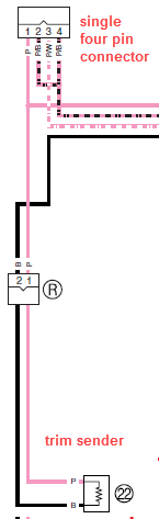
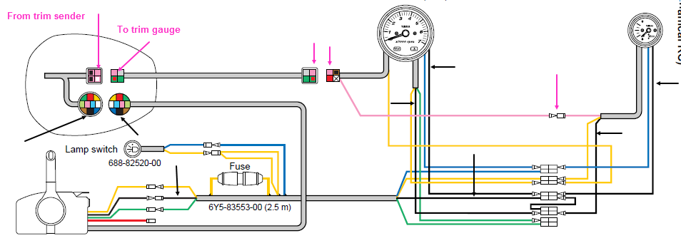
First, the tilt/trim function works well, but the trim gauge is motionless off the scale above the UP position. I've determined that the spring loaded lever on the trim sender is moving as it should. I'd like to check the electrical output from the sender near the engine as the first step in troubleshooting. Can anyone tell me the best place to intercept the wires to/from the sender under the engine cover?

Second, while checking out the engine wiring I discovered a 4-pin plug hanging freely. I see no obvious place for it to be connected. The four wires appear to be black, yellow, beige and light pink. The photo shows it propped up on the dip stick. Can anyone tell me what this is for or where it goes?
Mystery connection 1.jpg
 

boscoe99

Commander
Joined
Aug 22, 2013
Messages
2,060
What is the model of the motor? If it is indeed a 2006 or later model what is the date of production?
 

boscoe99

Commander
Joined
Aug 22, 2013
Messages
2,060
Is there no sticker on the other side of the clamp bracket that shows the month and year of manufacture?
 

boscoe99

Commander
Joined
Aug 22, 2013
Messages
2,060
The unused connector that is resting on the dipstick, does its wire harness go outside the motor via the rigging grommet?
 

HotTommy

Lieutenant Junior Grade
Joined
Mar 15, 2013
Messages
1,025
Boscoe99 - the date is 02/06
Yes, the bundle does go directly away from the engine at the rigging grommet.
 

boscoe99

Commander
Joined
Aug 22, 2013
Messages
2,060
I have not been asking these questions to make your life miserable. The situation is that Yamaha made a design change around the time your motor was built. The change was related to the four pin connectors that attached to a harness that ran out of the motor and up to the dash. Early models used two four pin connectors. Later models use one four pin connector. One of the wires in the four pin connector(s) is that for the trim gauge.
 

boscoe99

Commander
Joined
Aug 22, 2013
Messages
2,060
The trim sender is located on the clamp bracket. A component below the bottom cowling. Find the sender and then follow the wires into the bottom cowling. Then follow those wires inside the cowling, one of which, the pink one, leads to the single four pin connector.

Let me know what you find.


HotTommy

Lieutenant Junior Grade
Joined
Mar 15, 2013
Messages
1,025
Boscoe, I never doubted your intentions. I'll look into it tomorrow and report back. Thanks.
 

HotTommy

Lieutenant Junior Grade
Joined
Mar 15, 2013
Messages
1,025
I was able to trace the black/pink wires from the sender to a connection at the engine. Assuming the sender is a variable resistor, I connected an ohmmeter across the black and pink leads and moved the engine. The resistance changed with engine movement leading me to believe the sender may be working.

I then went under the helm and disconnected the 6-pin connector from the multifunction gauge that includes trim. It has a single pink wire and a black one. My guess is that the black is ground for all the gauge functions and I don't know if it is the same as the black wire from the sender. So I need to know how to check the trim signal arriving at the gauge to see if it is within expected limits.
 

boscoe99

Commander
Joined
Aug 22, 2013
Messages
2,060
The sender is a variable resistor.

All blacks are normally grounds. Can't imagine why it would not be on your boat.

You can measure the resistance on the pink wire at the dash. To any ground. The resistance should be the same at the dash as it is when measured directly at the sender connector.

This is what the arrangement would be if a typical Yamaha trim gauge were to be used.

 
Top