99 5.7L EFI OBD question

alldodge

Moderator
Staff member
Joined
Mar 8, 2009
Messages
42,633
MIL indicator light

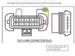
The MIL light is not going to cut it, you need a LED with a built in resistor. The built in resistor to cut done on the current the light will pull. Your MIL light in most cases is an incandescent bulb or an LED without a resistor. Go to Radio Shack or other, maybe an auto parts store may have one, get the correct LED. Then get a paper clip and test away

DLC with LED code reader.jpg
 

alldodge

Moderator
Staff member
Joined
Mar 8, 2009
Messages
42,633
Would be interested in comparing what your reading to the Rinda scan tool.

As for the regular bulb, I'm not chancing my ECM using one of those.
 

thumpar

Admiral
Joined
Jun 21, 2007
Messages
6,138
I would interest also. What cable are you using? I have thought about trying to justify getting a Rinda.
 

alldodge

Moderator
Staff member
Joined
Mar 8, 2009
Messages
42,633
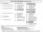
There are more entries then the MEFI-3 is set to read. Here is for MEFI-1, 2, 3 which are fairly primitive.

MEFI Codes.jpg
 

Fun Times

Moderator
Staff member
Joined
May 16, 2009
Messages
9,128
I know you say you don't like the new program and that it's jumpy and all along with the boat runs fine....But watching the video sort of seems to indicate otherwise mainly because due to all the "engine parameters" are jumpy but not the entire screen image itself.

Without being next to the engine listening to it, Just watching the battery volts rest at 11.8v and then drop to under 8 volts along with all the other parameters, would typically indicate a serious issue with the battery/charging system which should be around 12.7 range at rest or 13.8 volts while running.
 

Fun Times

Moderator
Staff member
Joined
May 16, 2009
Messages
9,128
If you look carefully at the lower left corner of the app screen, you will see the status indicator go red instead of blue. That indicated a loss of communication with the ECU temporarily or an error in the data checksum. Also you see that the rpm jumps to about 6000, highly unlikely ;-)

On another issue, I am starting to believe that the alternator is not working in this boat because the previous owner had two batteries and a built-in battery charger with switch installed. Smoking gun huh?
Lost communication due to a voltage issue was where I was thinking vs bad scanner program. If you suspect a bad alternator then you'll want to confirm that with a multimeter to help know if the scanner is working correctly or not.
 

alldodge

Moderator
Staff member
Joined
Mar 8, 2009
Messages
42,633
Those are just the trouble codes, which are a subset of the data I saw. There is a lot more data than that available. Or is that what you are saying?

There are very few sensors which are used by Merc. The fault codes are the only ones which can cause an issue for the motor so far as running. Agree there is other data available, but for most folks this has to be compatible.

mediafire.com link

Changed so its not an active link, but this wants to download a zip file. Now that is a risky issue for anyone not knowing where it comes from.

The loss of communication can be due to the impedance of the cable and connection/adapter/software. As before I won't use a incandescent bulb due to current possibilities.
 

achris

More fish than mountain goat
Joined
May 19, 2004
Messages
27,468
Very interesting thread, right up my street.

As for the jumpy data, all bets are off until the alternator is fixed and the ECU is getting full and proper voltage. The ECU internals uses 5v and 12v, and if the input voltage is low, then the subsequent 'stepped down' voltages will also be low. One of the first rules I learnt when I started on my career as a computer hardware engineer was 'check power supplies first'.... That rule has solved countless problems a lot of other people couldn't.

Troubleshoot the alternator and get the voltage up to 13.8-14.4, then have another look at the data stream.

Chris.......
 

thumpar

Admiral
Joined
Jun 21, 2007
Messages
6,138
The ECU may be able to run the engine at less than 12v but how would it produce the 12v need for serial communications? Serial communication is supposed to be +12v and -12V but most will read a +12v and 0v.

I used to build smart card read/writers. We would use a max232a and caps for the serial +12v/-12v to card's +5v/0v interface. Later on I started using a 1489 because it was cheaper and didn't need all the caps. The downside was it only produced +12v and 0v. A 1488 was needed to make the -12v. We got away without the -12v with most serial ports but some didn't like it and would cause issues kind of like what you see. If you can get the ECU full voltage it may help. I would like to see the guts of the cables like Rinda makes.
 

thumpar

Admiral
Joined
Jun 21, 2007
Messages
6,138
Good to know there are 2 versions of the ftdi. When I was messing with this stuff serial ports were just starting to go away on pcs so we didn't get into using the ttl version. I was all ready to try to find my cable but it is rs-232.
 
Top