Oshkosh1
Ensign
- Joined
- Jun 8, 2009
- Messages
- 968
Hi all...
I have points and I don't THINK the previous owner installed a reistor wire when the swap was made. I just remember seeing something that didn't seem right, but was buried under multiple layers of electrical tape...only the ends were exposed enough to see.
As this is a "composite" powerplant of sorts(early 70's engine/late 80's wiring)I've found the need to compare different schematics to discern/inperpet my wiring.
Bear with me...
Here's the current setup:
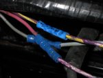
There's a purple/yellow wire running from the starter solenoid with a spliced in white wire painted purple/yellow to the + term. THAT seems correct(albeit sloppy).
There's a white wire painted (again)solid purple spliced onto the factory solid light purple(not painted)wire found within the wiring harness.
There's a grey wire to the -side...to the tach...no issues, tach works fine.
I turned the key to the "Run" position and measured 12.5V at the terminal end of the solid purple wire and as I understand it, I should be reading about half of that...correct?
The other wire reads "0"...so other than the bu-shwa-zee wiring re-paint...this seems normal.
Here's a pic:

So...assuming this spliced in replacement ISN'T a resistor wire, and I DO need one. Where can I find some?
Thanks.
I have points and I don't THINK the previous owner installed a reistor wire when the swap was made. I just remember seeing something that didn't seem right, but was buried under multiple layers of electrical tape...only the ends were exposed enough to see.
As this is a "composite" powerplant of sorts(early 70's engine/late 80's wiring)I've found the need to compare different schematics to discern/inperpet my wiring.
Bear with me...
Here's the current setup:
There's a purple/yellow wire running from the starter solenoid with a spliced in white wire painted purple/yellow to the + term. THAT seems correct(albeit sloppy).
There's a white wire painted (again)solid purple spliced onto the factory solid light purple(not painted)wire found within the wiring harness.
There's a grey wire to the -side...to the tach...no issues, tach works fine.
I turned the key to the "Run" position and measured 12.5V at the terminal end of the solid purple wire and as I understand it, I should be reading about half of that...correct?
The other wire reads "0"...so other than the bu-shwa-zee wiring re-paint...this seems normal.
Here's a pic:

So...assuming this spliced in replacement ISN'T a resistor wire, and I DO need one. Where can I find some?
Thanks.


