Gimbal Bearing Compatibility and Source?

achris

More fish than mountain goat
Joined
May 19, 2004
Messages
27,468
That's normal, just make sure the area is clean and it'll be fine..
 

76SeaRay

Lieutenant Junior Grade
Joined
Aug 24, 2017
Messages
1,071
Ok, thanks. The new bearing came in today. That was fast, I only ordered it yesterday early afternoon. It looks of higher quality and is built differently from the previous two in the area of the inner retainer rings. It has the inner bearing numbers on the inner race and says the inner bearing was made in Italy where the other two did not have any identifying marks. The chamfer on the outer race is a bit larger than the other two bearings which should be better during installation. The bag has Mercury Marine printed on it.
 

poconojoe

Lieutenant Commander
Joined
Sep 10, 2010
Messages
1,966
This is why I only use oem when it comes to critical parts. Especially parts that are not easily accessible.

You have to pay a bit more, sometimes a lot more, but in the end you know it will fit and perform as designed by the engineers.
 

76SeaRay

Lieutenant Junior Grade
Joined
Aug 24, 2017
Messages
1,071
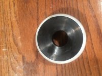
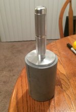
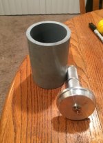
Taking advice above, I made a driver out of a piece of a 3 inch schedule 80 pipe and my bearing and seal driver set from Harbor Freight. In the pictures, the black driver ring is from the Marine Tech kit. It drives the grease seal ok but as you can see in the picture it is too small to drive the gimbal bearing. Anyway, the other pictures show the DIY approach with the pipe and the bearing driver. I froze the bearing for 4 hours. I used the Marine Tech driver to lightly tap the bearing to get it started then switched to the DIY driver and it went right in with no problem. After it was in, I was able to "gimbal" the bearing with the alignment tool. It took a bit of force but nowhere near what it took with the apparent after market bearings. Tomorrow I will try to align the engine again and see if the new OE bearing makes it easier to align.

Marine Tech Driver.jpg

DIY Driver 1.jpg

DIY Driver 2.jpg
 

1960 Starflite

Petty Officer 1st Class
Joined
Jun 23, 2011
Messages
387
For what it's worth. Years ago (late 1980's) I had to replace the engine coupling on my 1979 Century 140 inline 4 cyl. While doing so I replaced the Bearing Cartridge (Gimbal) by tapping it sideways and pulling it out. Replaced with new by inserting into outer race and winding/tapping back in place. Now a days they (Mercury) mount the bearing so one can't replace just the cartridge. I used SKF or Fafnir cartridge. Well it lasted until I had to replace bellows last year. Just Sayin
 

Lou C

Supreme Mariner
Joined
Nov 10, 2002
Messages
13,070
Interesting discussion. I have a grease-able one my mechanic installed back in 2005 and its been fine all these years because the bellows didn't leak, I had a new bellows installed then and replaced that one in 2016. Its good to know the sealed ones last, I was skeptical about them but then again I have sealed front wheel bearings on all 3 of our Jeeps and have not had to replace one (oldest is at 23 years old and 180,000 miles) same with the sealed ujoints.
 

76SeaRay

Lieutenant Junior Grade
Joined
Aug 24, 2017
Messages
1,071
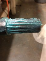
Ok, so absolutely no question that the OE gimbal bearing makes it easier to align. I can feel and see the movement in the gimbal when whacking on it side to side and top to bottom. The other ones just would not move. That said, I seem to be able to get the alignment close but not quite there. By the way, the rear mounts are torqued to 38 ft-lbs and use the double wound coil spring. The picture below shows the witness marks on one side of the alignment bar and you can see it engages the splines up to the step in the alignment bar (about 2 inches into the splines). It does slide in stiff but seems close. Since my drive is completely disassembled, I tried the driveshaft and it does not go in all the way. It stops short of the o-rings so more alignment adjustment is needed. I am doing this on the chain hoist so I suspect that I need it set down on the motor mounts and fine tuned with the steel motor mount threaded adjustment.

Since this exercise of getting the engine aligned at this time is only to locate the wood front motor mount landing pads with the metal engine motor mounts at center of travel, is this alignment being close good enough to build the final wood motor mounts?

Alignment Bar Depth.jpg
 
Last edited:

achris

More fish than mountain goat
Joined
May 19, 2004
Messages
27,468
is this alignment being close good enough to build the final wood motor mounts?
Yes.

And you have miles too much gear in that couple. That's possible why the yoke won't go all the way in.
 

76SeaRay

Lieutenant Junior Grade
Joined
Aug 24, 2017
Messages
1,071
So, are you saying I may have the wrong coupler? How much should the driveshaft go into the coupler? If I am close enough for gauging the motor mounts, then I will go ahead and pull the engine back out so I can double check the coupler.

BTW: My driveshaft measures 8 1/2 inches from the tip to the center of the first o-ring.
 
Last edited:

Scott06

Admiral
Joined
Apr 20, 2014
Messages
6,782
So, are you saying I may have the wrong coupler? How much should the driveshaft go into the coupler? If I am close enough for gauging the motor mounts, then I will go ahead and pull the engine back out so I can double check the coupler.

BTW: My driveshaft measures 8 1/2 inches from the tip to the center of the first o-ring.
no he is saying you have too much grease on the tool and coupler, thats why drive shaft wouldn’t go in.
I think autocorrect or Fosters correct messed up his post.
 

achris

More fish than mountain goat
Joined
May 19, 2004
Messages
27,468
no he is saying you have too much grease on the tool and coupler, thats why drive shaft wouldn’t go in.
I think autocorrect or Fosters correct messed up his post.
Yes, reread my post. It doesn't make much sense. Here it is, correctly... (and you are right, autocarrot got me 🤦)

Yes.

And you have miles too much grease in that coupler. That's possible why the yoke won't go all the way in.
 

76SeaRay

Lieutenant Junior Grade
Joined
Aug 24, 2017
Messages
1,071
Thanks. I cleaned my driveshaft (including using a wire wheel) and as much of the coupler as I could. When I slide the driveshaft in, it doesn't appear to engage the gimbal bearing inner race before it stops in the splines (about 1/2 inch engaged). So, that kind of eliminates the gimbal alignment but speaks to a problem with the mating of the splines. Looks like I need to pull the engine so I can try cleaning the coupler better and try sliding the driveshaft into the coupler free of any other parts. I wonder if there is a rust spot or burr inside the splines of the coupler preventing the driveshaft from sliding any further. I will measure the motor mounts then I can pull the engine.
 

76SeaRay

Lieutenant Junior Grade
Joined
Aug 24, 2017
Messages
1,071
Well, now I am really perplexed. I pulled the engine forward and up then turned it to the side to slide the shaft in without any other parts. The driveshaft slides right in all the way with no binding or hydraulic lock. So, I am at a total loss as to what to do. I think I will have to give up on this for now and get the floor and stringer restoration finished then I can set the engine fully onto solid mounts and try fine adjustments.
 

achris

More fish than mountain goat
Joined
May 19, 2004
Messages
27,468
Does the driveshaft (yoke) slide all the way into the gimbal bearing with the engine out of the way?

Chris.......
 

76SeaRay

Lieutenant Junior Grade
Joined
Aug 24, 2017
Messages
1,071
Yes, it slides all the way into the gimbal bearing. I did notice just a very, very slight catch to it as it slides over the transition from the smaller diameter up to the race surface just in front (about 1/4 inch) of the front o-ring.
 
Top