Ignition switch

LEE MICHNAL

Seaman Apprentice
Joined
Feb 13, 2016
Messages
39
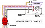
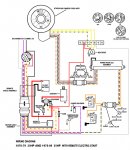
I have a 1976 35 hp evenrude, electric start, I cannot get it to start with the key switch, but it will start and run if I jump the starter
I purchased a new ignition switch and wired it , when I try to start it the wires to the ignition get hot but if I unhook the orange wire
It the wires don't heat up, and it will run when jumped, I have 5 wires from the motor to the switch. Orange or red, yellow/black. Blue/white and 2 blacks
On the switch I have. C. S. A. B. M. M. Could someone please help me thanks Dave. Davidmichnal@aol.com
 

emdsapmgr

Supreme Mariner
Joined
Dec 9, 2005
Messages
11,551
Your original factory key switch is the older variety, with a separate choke switch just below the key switch.
From what I see from my 76 service diagram: one of the M terminals goes to battery ground. The other M provides the kill to the power pack (black)
The B (battery) goes through the main wire harness fuse direct to the battery pole on the start solenoid. Purple/red wire
the A (accessory) is probably the (purple) Two wires connect, one to the horn, the other to the separate choke switch
the S (start) goes to the start solenoid. May be a white wire.
Factory switches don't have a "c" terminal.

It is possible you don't have an original factory key switch. If so, it's possible the "C" terminal may be for the choke, which may be part of the key switch. One of the later push-to-choke type switches (not a factory switch for 1976.)

If you look at the top thread on page 1, called "top secret files" you will find a partial set of wiring diagrams for various 1976 engines. That may also be helpful to you.
 
Last edited:

F_R

Supreme Mariner
Joined
Jul 7, 2006
Messages
28,226
No Title

It goes like this. The "C" terminal is for the push-to-choke feature, not used if you follow the original layout which has the toggle switch for choke.
 

Attachments

  • photo154226.jpg
    photo154226.jpg
    116.6 KB · Views: 0
Last edited:

LEE MICHNAL

Seaman Apprentice
Joined
Feb 13, 2016
Messages
39
Hello, thanks your input it helped but the problem I have right now is the wires in the harnes are not the same colors as the diagram
I have 5 wires, 2 black ones-- 1 blue/white wire. 1 yellow/red. 1- that is orange red looking.
Would you be able to tell me where these would go on the plug which has. 5 wire connections. C a s m b m
Dave
 

F_R

Supreme Mariner
Joined
Jul 7, 2006
Messages
28,226
It would appear that you do not have a 1976 control. I looked through my collection and did not find any with the colors you state. That doesn't mean it doesn't exist--just that i don't have it.

My suggestion at this point is look at the wires at the engine end and see where they go. If we knew that, we could answer the question (maybe).


EDIT: I'm starting to think you don't even have an Evinrude control. Maybe a durn Yamaha or Suzuki or something, modified to work?
 
Last edited:

LEE MICHNAL

Seaman Apprentice
Joined
Feb 13, 2016
Messages
39
HELLO FR, I wanted to get back with you on this ignition switch we were talking about, I purchased the switch for a 1976 35 hp evenrude it has 6 posts
A B C S M M. And the wires to the ignition switch from the motor are 1 reddish one. 1 yellow red. 1 bluefish one 2 black ones
Here is where they go , One black to a coil,, other black to a black thing that says cd2. the red to the big bolt on side of the selonoid and from there to an
Inline fuze then to a terminal block on engine then into the flywheel area. The blueish to the auto choke, the yellow red to small screw on selonoid then to
A button switch on the engine. Would you be able to tell me how to hook the wires to the new ignition switch.
Here are some pics. Of. The cd2 and the button on the block.
 

Attachments

  • image.jpeg
    image.jpeg
    47.7 KB · Views: 0
  • image.jpeg
    image.jpeg
    58.5 KB · Views: 0
  • image.jpeg
    image.jpeg
    58.1 KB · Views: 0
  • image.jpeg
    image.jpeg
    52.3 KB · Views: 0
  • image.jpeg
    image.jpeg
    56.4 KB · Views: 0

F_R

Supreme Mariner
Joined
Jul 7, 2006
Messages
28,226
No Title

OK, I am posting another diagram. I think you can figure it out from it. Here is the bottom line---what is required to run the motor.
A wire from the fuse to the switch "B" post, normally red with purple stripe.
A wire from the small terminal on the start solenoid to the switch "S" post, normally white. Second small solenoid terminal goes to micro switch (safety switch)
A wire from the choke to switch "C" post, normally purple with white stripe
A grounded wire to one of the "M" posts, normally black
A wire from the CD2 power pack to the other "M" post, normally black with yellow stripe.
If one of the "M" posts is marked or raised, or in center, use that one for the black/yellow stripe from CD2 power pack
If there are any solid purple wires, put them on the "A" post
EDIT: You mention a wire going to the terminal strip to the flywheel area. That should be grey---a tachometer lead. I don't know what is going on with yours
 

Attachments

  • photo239439.jpg
    photo239439.jpg
    198.5 KB · Views: 0
Last edited:
Top