Install Trim Limit & Trim Senders

Status
Not open for further replies.

golbrick7

Seaman Apprentice
Joined
Aug 17, 2010
Messages
42
Bought a new set of Trim Limit and Trim Senders and want to by-pass the existing wiring due to corrosion, breaks in current wiring, and rodent chews. Have two wires coming from each of the senders. Can anyone help in connecting these directly to the battery, gauge and pump? Sure would appreciate it.
Thanks in advance,
golbrick7
 

QC

Supreme Mariner
Joined
Mar 22, 2005
Messages
22,783
Re: Install Trim Limit & Trim Senders

Hey golbrick, welcome aboard!! I have moved this to the I/O section. It would be best of you gave us some more info on your specific drive setup so we could focus the response. Good luck!
 

golbrick7

Seaman Apprentice
Joined
Aug 17, 2010
Messages
42
Re: Install Trim Limit & Trim Senders

Thanks for the Welcome to iboats. Below you will find the info on my set-up. Will attempt to attach a drawing also, if it's not too big.

1976 Hammond 19' Ski Boat - use for fishing and pleasure
Engine: 165hp In-line 6 MerCruiser Marine
Out Drive: 1.6R Pre-Alpha, 1970-1977 Model 165 R-Drive
Rack, Pinion, Cable Steering System (Teleflex Marine)

Hope this helps in trying to install my Trim Limit & Trim Senders, by-passing the current wiring harness.

Now to try and add the attachment showing my set-up.
WELL, couldn't get it to upload soo: 2 Black wires coming from each sender. Grounding bar bonded to engine, Trim/Tilt pump, battery, In-Line 6 165hp engine, ignition, gauge.

Thanks in advance,
golbrick7 (Joe)
 

golbrick7

Seaman Apprentice
Joined
Aug 17, 2010
Messages
42
Re: Install Trim Limit & Trim Senders

Can anyone help with this rewiring job?
Sure would be appreciated.
 

stonyloam

Vice Admiral
Joined
Mar 13, 2009
Messages
5,827
Re: Install Trim Limit & Trim Senders

This might help for the trim sender: http://www.boatfix.com/merc/Servmanl/13/13E4R2.PDF Bypassing the trim limit switch wires would be more of a problem. You need to hook one of the wires to the purple/white wire connector and the other to the connector with the two blue/white wires. The problem is that to do it correctly you have to remove the bellows and bellhousing. You might try extending the wires and running them over the transom in to the engine compartment.
 

golbrick7

Seaman Apprentice
Joined
Aug 17, 2010
Messages
42
Re: Install Trim Limit & Trim Senders

Thank you for the reply. What I'd really like to do because the existing wiring is so bad is to by-pass it altogether. I've install the new Trim Sender and Limit switches on my lower unit and have gone over the transom with the wires from each. What I really need to know is how to run directly to the Trim Pump, Battery, Ignition and gage. I have two black wires coming from of the Sender and Limit switches (niether switch has any color coding on them), and a ground block bonded to the engine. Is it possible to do it this way? By the way, thanks for the PDF file.
golbrick7 (Joe)
 

bigdan1

Petty Officer 3rd Class
Joined
Aug 9, 2010
Messages
95
Re: Install Trim Limit & Trim Senders

I have the same problem ....i`m looking closely at the replies ...:)

removed the outdrive , still no reach to the wires ...they wont move at all .
 

golbrick7

Seaman Apprentice
Joined
Aug 17, 2010
Messages
42
Re: Install Trim Limit & Trim Senders

Good evening BigDan1:
Know what you mean. It's been a real bugger. Sure hope someone can help with getting things to work.
golbrick7 (Joe)
 

Don S

Honorary Moderator Emeritus
Joined
Aug 31, 2004
Messages
62,321
Re: Install Trim Limit & Trim Senders

You have a completely different setup as to what is in manual #13 That is the manual for a 90 to 97 3.0L engine.

Here is the wiring diagram from manual #2 74-77 engines and drives.
look at your trim pump and see if you have 1 or 2 trim solenoids. that will determine which wiring diagram to use.
 

Attachments

  • single solenoid.jpg
    single solenoid.jpg
    114.8 KB · Views: 7
  • double solenoid.jpg
    double solenoid.jpg
    83.8 KB · Views: 6

golbrick7

Seaman Apprentice
Joined
Aug 17, 2010
Messages
42
Re: Install Trim Limit & Trim Senders

Don S.
I have a single solenoide and a two button switch (up/down). Diagrams show 3 button switch.
 

rodbolt

Supreme Mariner
Joined
Sep 1, 2003
Messages
20,066
Re: Install Trim Limit & Trim Senders

the limit switch is just that, its an ON or OFF switch, you MUST use the 3 button switch OR two switchs.
the trim limit switch is wired in series with the TRIM switch, the thrid button OR second switch is wired in parralell and will bypass the trim limit switch for TILTING when beaching or trailering.
the TRIM position sender, its NOT a switch, is a variable potentiometer.
its NOT polarty sensitive it just places a variable resistance between the gauge sense terminal and ground.
vary the resistance in the sense circuit and you vary the current flow.
vary the current flow and the opposing magnetic field in the analog gauge varys.
vary the opposing field and you alter the needle position.
yes virginia, its about that simple.
to replace the switch and sender you must simply follow the steps in the correct factory shop service manual.
 

golbrick7

Seaman Apprentice
Joined
Aug 17, 2010
Messages
42
Re: Install Trim Limit & Trim Senders

Appreciate the feedback....I'm really only interested in my tilt position of my outdrive, so having one solenode, one up/down switch, and the two black wires from the sender, how would I hook up my guage to tell me when my lower unit is up or down when trailoring/beaching or in shallow water? Any help would be appreciated.
Joe
 

rodbolt

Supreme Mariner
Joined
Sep 1, 2003
Messages
20,066
Re: Install Trim Limit & Trim Senders

the trim limit switch is a SAFTY feature. needs to be there.
the trim position sender DOES NOT go to anything trim switch or solinoid related.
 

PitchFork

Petty Officer 1st Class
Joined
May 28, 2009
Messages
313
Re: Install Trim Limit & Trim Senders

I know a lot of boaters on this forum do not even use the trim limit switch or senders. As someone like Don has said in the past Seat of the Pants feel. I have not had working ones since I purchased the boat 3+ years ago. From what I have read here on the forum over the last three years they do not last long and are a PITA to change.

Although I may install new ones when I change the bellows this winter.

Outdrive and bellhousing have to be removed if I remember right. I will found out this winter.
 

rodbolt

Supreme Mariner
Joined
Sep 1, 2003
Messages
20,066
Re: Install Trim Limit & Trim Senders

like I said, the trim limit is SAFTY feature.
can ya run it bypassed, see it all the time.
if its in my shop it gets replaced or the work stops.
when your paying a dealership 85/hr to repair a rig it must be done PER the service manual or the lawyers have the possibility to make another beemer payment,or 3.
the reason for the trim limit is to alert the operator that the drive is tilting beyond the side supports on the shield assy an under power it is possible to break the gimbal housing or ring or both resulting in a loss of control and leading to injury.
its right there in the manuals in bold print.
so Mr shumuckatlly comes in with his queen mary, the lower shift cable needs replacing.
I find the trim lmit switch is bad during the course of dissasembly.
remember, this is a SAFTY item AS noted in the FACTORY shop service manual.
now Mr shumuck has 2 options, repair it per the service manual or I can load all the parts in the back of the boat and he can run it to one of the local jack legs that dont have insurance nor factory training and support.
it all comes down to whats going to happen in a court IF something happens and an attorney is looking for a paycheck.
its also why when I get a rig in that we dont regularly service I inspect EVERYTHING I can for USCG compliance, is the flame arrestor there and not beat up,starter correct,alt correct,fuel system correct and not cut up.
if its a safty item that could result in serious bodily injury or death it either gets fixed or I load up the parts and it leaves.
a fellow Tech some years back learned this the hard way.
he worked on a rig with a non compliant fuel system, noted the non-compliance and released it with a signed work order noting the non-compliance.
some weeks later the boat burned and burned 2 others in the slip.
fellow tech's insurance got to pay for 3 boats and the dock damage.
its kinda like here on the net, can I tell you how to bypass nuetral start interlocks,shift interlocks or emergency stop switchs? yep all day long. will I ? nope.
only way thats going to happen is for testing and troubleshooting ONLY.
 

Jet Wrench

Petty Officer 3rd Class
Joined
May 26, 2010
Messages
97
Re: Install Trim Limit & Trim Senders

I am in total agreement with RB. If your a Tech, safety is your primary concern, as well as the liability issue. If you get sued, your done. If you have a paper trail with work done per the manuals and policies and procedures, you don't have anything to worry about. I have been an Aviation Engineer/Technican for almost 30 years and do everything by the book, as it should be done. I won't install a part unless it has a paper trail with a history back to the manufacturer. I don't lose any sleep at night worrying about an airframe that I have released for flight, thinking it may end up a "smoking hole" in the ground somewhere! You're work quality should not be dictated by who is looking over your shoulder. It is your personal dedication to knowing the work has been done correctly. If the customer wants to cut corners, thats his business and you shouldn't get involved. Period. I am a Craftsman by trade and very proud of the fact that my work speaks for itself. I'm off my soapbox. My hat is off to you RB!

I just fixed my trim system yesterday. I was fortunate that the trim interrupt for trim up is working correctly, per the manual. Can you bypass the circuit and get by, sure you can! When you burn up your engine due to weak cooling due to pump cavitation, you'll be kicking yourself for not spending the labor hours or rate to fix the system correctly the first time! There is a reason for $90.00 + per hour shop rates. It's rather inexpensive insurance knowing the work had been done correctly the first time. Mechanics/Technicians get a bad rap. They continually have to clean up messes left behind by the owner who never inspects his craft for pending maintenance issues, much less taking the tasks at hand himself!

Jet Wrench

Trim/Tilt work performed yesterday:

Thanks for the contributions to my trim issue. Good stuff on the forum to glean information from. I removed the trim motor and solenoid relays, cleaned and burnished all connections. Found that both relays had high resistance when latched when tested on the bench. I was able to disassemble both relays and clean/burnish the contacts (I'm a cheap SOB!, saved $40.00), they work great now. I removed the motor armature and brushes, burnished the armature and cleaned the housing. The brushes were in good shape, no issues. Easy to do, a little time consuming though. I lubricated shaft bushings and re-assembled the motor, tested on the bench, nice and smooth with good torque. These early motors are built very stout! It is fair to say they are much better quality than what you can buy new today. No plastic to get brittle and break. I was fortunate, the pump has nice clean fluid with no need to top off. I did replace the o-ring (packing) between the pump and motor assy's when going back together.

After re-assembly, turned on the master power and got nice linear up/down trim actuation from the thottle trim switch with good indication on the indicator and correct trim up operation with the skeg stopping at the right height before cavitation can occur. The trailer tilt operation worked correctly for up actuation, but did not work in down. Found the down wire from the switch was disconnected. The previous owner had worked on the wiring at some point and really FUBAR'ed the trim/tilt wiring at the instrument panel. I believe he tried to bypass the bad relay issue with no success and left it that way. I cleaned up his rat's nest and now have proper tilt/trim operation!

It ended up being four different issues:

BAD TRIM RELAYS
CORRODED TRIM MOTOR EXTERNAL TERMINALS
CORRODED TRIM MOTOR INTERNALS
COBBED WIRING

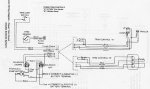
Thanks for your help with the diagrams.

JW
 
Last edited:

Bondo

Moderator
Staff member
Joined
Apr 17, 2002
Messages
71,148
Re: Install Trim Limit & Trim Senders

how would I hook up my guage to tell me when my lower unit is up or down when trailoring/beaching or in shallow water?

Ayuh,.. Wire the Sender, to the Gauge....

Or,... Learn to use the Seat of yer Pants...
 

dubs283

Vice Admiral
Joined
Jul 27, 2005
Messages
5,337
Re: Install Trim Limit & Trim Senders

how would I hook up my guage to tell me when my lower unit is up or down when trailoring/beaching or in shallow water?

folks here a gonna tell you how to do it til they're blue in the face, and by the looks of this thread, you aren't going to listen to them

so my advice to you is - start a new thread asking which mercruiser service manual you need for your drive

in this post you will need to include the make/model of your engine/drive package and a model year

a serial number for the drive will be the best info

if you are patient, someone may post a link to a website where you can download the proper OEM manual for your drive

in the manual, you must read exactly how to properly install your trim senders - if you follow the instructions in the manual, you will get the job done correctly
 

golbrick7

Seaman Apprentice
Joined
Aug 17, 2010
Messages
42
Re: Install Trim Limit & Trim Senders

Gentlemen: I first would like to say thank you for your responses. My intention was not to do anything unsafely or attempt anything that could cause a safety hazard on the water. When I purchased my boat the wiring was in terrible shape and was trying to figure out a way to by-pass it while thinking it would solve the problem. iboats has been great in passing along good information and hope this thread hasn't created a situation where advise won't continue to flow. I've decided not to worry about including a guage or connecting the sensors. Please except my apologies.
Respectfully,
Joe
 

voisin1972

Recruit
Joined
Aug 28, 2020
Messages
4
Re: Install Trim Limit & Trim Senders

You have a completely different setup as to what is in manual #13 That is the manual for a 90 to 97 3.0L engine.

Here is the wiring diagram from manual #2 74-77 engines and drives.
look at your trim pump and see if you have 1 or 2 trim solenoids. that will determine which wiring diagram to use.
on single diagram where the "Meter" goes for the tilt ?
 
Status
Not open for further replies.
Top