kill switch, ignition ? 73 40hp

393Clevor

Petty Officer 1st Class
Joined
May 18, 2019
Messages
209
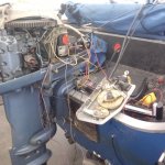
In the final stages of getting this old girl ready.. I am missing the motor plug part of the controller so I just hacked off the end of the harness coming from the controller.. this is what I have figured out so far... ,where I get stomped is this kill switch part of it..
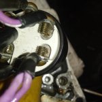
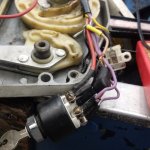
I got the main power (red) hooked to the (+) side of the solenoid, Purple/White to the electric choke, Yellow and red to the starter solenoid, Black (-) ground, Purple is a key on hot wire (+) must go to the gen or rectifier, Black/Yellow seems to be the kill switch in the off position it's grounded.. there is another wire a gray one that just goes thru to the pig tail connection and a brown wire that goes to an alarm inside the box
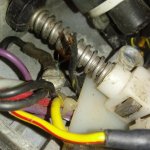
what has me baffled is this cut out switch.. I need two ground wires to kill it, the way it is now with just one kill wire it only kills one set of points..#2 is still sparking and it is connected to the cut out switch... Do they kill these engines with just one cylinder?.. seems I need a controller with two keyed grounds to kill both cylinders.. what I'm I missing?
 
Last edited:

393Clevor

Petty Officer 1st Class
Joined
May 18, 2019
Messages
209
I'm looking at another diagram and it shows a kill switch that shorts the two sets of point out together. when one is open the other is closed.. keeps them grounded out until you let off the kill switch.. man who thought up this stuff..
 

F_R

Supreme Mariner
Joined
Jul 7, 2006
Messages
28,226
Purple is not used, except to provide power from key switch to choke switch.

Grey is a tachometer signal lead (not uses on your motor)

Tan is an overheat alarm (not used on your motor because it has no temp sensor)

Motor is killed (both cylinders) by connecting both sets of points together (two black wires, if you had the correct cable) They go to the two "M" terminals on the key switch. "M" terminals are not otherwise grounded. And "who" goes way back to 1958.

The vacuum cut-out switch has absolutely nothing to do with killing (stopping) the motor. It is there to cut out one cylinder in event of high vacuum caused by a motor in run-away mode. Yes, the center terminal is used as junction point for one of the two kill wires leading up front, but it does nothing unless in run-away mode.

Like I said, this is all very old tech and well known. You are being confused by using an incorrect cable/colors
 

393Clevor

Petty Officer 1st Class
Joined
May 18, 2019
Messages
209
I think this controller is for a 75 Johnson 40hp.. it only has one kill port on the switch.. also found another black/yellow wire cut off inside the controller .. wth is going on ..
 

Attachments

  • photo337914.jpg
    photo337914.jpg
    141.6 KB · Views: 0
  • photo337915.jpg
    photo337915.jpg
    140.9 KB · Views: 0

393Clevor

Petty Officer 1st Class
Joined
May 18, 2019
Messages
209
Purple is not used, except to provide power from key switch to choke switch.

Grey is a tachometer signal lead (not uses on your motor)

Tan is an overheat alarm (not used on your motor because it has no temp sensor)

Motor is killed (both cylinders) by connecting both sets of points together (two black wires, if you had the correct cable) They go to the two "M" terminals on the key switch. "M" terminals are not otherwise grounded. And "who" goes way back to 1958.

The vacuum cut-out switch has absolutely nothing to do with killing (stopping) the motor. It is there to cut out one cylinder in event of high vacuum caused by a motor in run-away mode. Yes, the center terminal is used as junction point for one of the two kill wires leading up front, but it does nothing unless in run-away mode.

Like I said, this is all very old tech and well known. You are being confused by using an incorrect cable/colors

I need a different switch by the sounds of it..
 

393Clevor

Petty Officer 1st Class
Joined
May 18, 2019
Messages
209
I can't find any wires that connect together in the off position from the switch.. I was looking for that when I stated wiring this up.. all I got is a black/yellow that gets grounded in the off position and open in the on position.. maybe have to hook up a couple of relays to do this.. I got a bunch kicking around.. I don't have any other switches..
 

393Clevor

Petty Officer 1st Class
Joined
May 18, 2019
Messages
209
all I have is 4 pin relays.. got a 5 pin coming that will work.. with no power on the relay it will close two connectors with power it will open them.. good enough I think.. got two coming, spare is always good to have..
 

393Clevor

Petty Officer 1st Class
Joined
May 18, 2019
Messages
209
By the way thanks everyone.. I know I'm a pain in the butt..
 

F_R

Supreme Mariner
Joined
Jul 7, 2006
Messages
28,226
And you are over thinking this

Black/yellow goes to one "M" terminal
Other "M" terminal is grounded
(AS IT IS NOW)

UN-ground the one "M" terminal nd connect that terminal to one set of points.
Connect the other "M" terminal to the other set of points.

When you turn the key off, the two "M" terminals connect together, which connects the two sets of points together, killing the ignition. How much simpler can it get?
 

393Clevor

Petty Officer 1st Class
Joined
May 18, 2019
Messages
209
And you are over thinking this

Black/yellow goes to one "M" terminal
Other "M" terminal is grounded
(AS IT IS NOW)

UN-ground the one "M" terminal nd connect that terminal to one set of points.
Connect the other "M" terminal to the other set of points.

When you turn the key off, the two "M" terminals connect together, which connects the two sets of points together, killing the ignition. How much simpler can it get?

My switch does not have that.. not over thinking.. that was the first thing I looked for .. I have both manuals here the 73 rude and the 75 Johnson, they both show dual m connections at the switch, mine does not..
 

393Clevor

Petty Officer 1st Class
Joined
May 18, 2019
Messages
209
Ok you're right I had to go back and take it all completely apart and actually take a picture to see it.. (my eyes are bad) but there is two M connectors one is grounded the other goes to the blk/burp wire.. the harness only had one blk/burp so I'll use the gray wire for the second set of points... that's what had me all missed up there is only one dlk/burp wire in the harness.. I'm good now.. Thanks..
 

393Clevor

Petty Officer 1st Class
Joined
May 18, 2019
Messages
209
I got it.. lol done!! I used the brown wire that feed the alarm it was long enough to solider to the remaining black wire left after I cut the ground.. Reason I take lots of pics my eye site is bad.. I can zoom in and see..
 

Attachments

  • photo337929.jpg
    photo337929.jpg
    89 KB · Views: 0
  • photo337930.jpg
    photo337930.jpg
    120.9 KB · Views: 0

F_R

Supreme Mariner
Joined
Jul 7, 2006
Messages
28,226
I knew you could do it. Anybody smart enough to rig up a relay is smart enough to do it right. Congrats.
 

393Clevor

Petty Officer 1st Class
Joined
May 18, 2019
Messages
209
what threw me was I have a 73 Rude and 75 Johnson both 40hp and both manuals show two wires coming from the points going to the switch so I figured when connected together it kiils the spark, when one set of points is open the other is closed so if you connect the two it's grounded.. but the wiring harness and controller I have doesn't support that.. But it does now..

Again thanks all..
 
Top