Looking for input

stan2076

Seaman
Joined
Jan 8, 2015
Messages
51
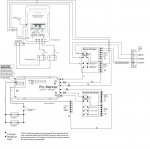
I'm adding AC power to my boat. Using the manufacturers wiring diagrams I created the proposed schematic below. I was hoping to get some input as to the "correctness" of my proposed setup. Hopefully it is readable if you zoom in.

The "Shore AC Panel" and "Inverter AC Panel" are Blue Sea 3116 surface mount panels. I got a good deal on the panels, but am wondering if I may have issues with running two ELCI's for any reason?

The ProNautic charger I have is actually the 1250P. I only have 30 amp power at my slip so the 50amp charger could potentially trip a breaker. I also got the 1250P for very little money but will swap it out for a lower amperage charger if needed.

Thanks!
Stan


boat wiring.jpg
 

alldodge

Moderator
Staff member
Joined
Mar 8, 2009
Messages
42,745
First this is my opinion only and approving or disapproving anything

I'm assuming that the two separate 12DC ground busses are actually connected together.
Also assume the four batteries are actually 2 banks of batteries, (Bank one - 1 single starting, Bank two - 2 deep cycle)

According to the 1250 manual it requires a 16amp breaker. My guess would be it takes no more then 110VAC to produce 50amp 12VDC output. The 50amp is spread across the 3 banks.

I see using two different panels as an issue for the possibility of having shore power and inverter power turned on at the same time. If you used two double breakers with a bar (shore power/Generator) setup would be better IMO.
attachment.php


Edit: and sorry almost forgot :welcome: to iboats
 
Last edited:

stan2076

Seaman
Joined
Jan 8, 2015
Messages
51
First this is my opinion only and approving or disapproving anything

-- Understood, thanks for taking the time to look it over. Mainly concerned that I don't create a dangerous condition.

I'm assuming that the two separate 12DC ground busses are actually connected together.

-- That's correct, they'll both be connected at the engine.

Also assume the four batteries are actually 2 banks of batteries, (Bank one - 1 single starting, Bank two - 2 deep cycle)

-- Actually, there's three banks. The trolling motor battery and engine battery will be charged by the 1250P and the house batteries in parallel will be charged by the Inverter/Charger

According to the 1250 manual it requires a 16amp breaker. My guess would be it takes no more then 110VAC to produce 50amp 12VDC output. The 50amp is spread across the 3 banks.

--Thanks for pointing out the breaker size, I missed that, I was assuming something larger.

I see using two different panels as an issue for the possibility of having shore power and inverter power turned on at the same time. If you used two double breakers with a bar (shore power/Generator) setup would be better IMO.

-- Yes, I agree that that is probably the most positive way to know that there is only one source. I was going by the inverter manual which states:

TRANFER SWITCH ? The TruePower Combi includes an internal, automatic 30 amp AC
Transfer switch that senses the presence of AC shore/station power. Upon connection
to a shore power/shore station source, the Combi will switch from INVERTER mode
(providing AC power via DC battery source) to CHARGE mode, automatically. This switch,
in compliance with ABYC E-11, disconnects the neutral AC lead from the AC ground when
in shore/station power mode.

I was thinking about the setup you described with a single panel and a manual transfer switch but was having trouble visualizing how avoid creating a loop where the inverter would be feeding the breakers that feed the chargers. To avoid that, one would have to ensure that the charger breakers were manually switched off before transferring from shore to inverter power. I'm sure there's probably a way around that that I don't know about. In my setup I put the breakers for the chargers in the first panel so they are de-energized when shore power is removed and are not on the output side of the inverter.

Edit: and sorry almost forgot :welcome: to iboats

-- Thank you very much!!

By the way, here's my Dodge...

pw.jpg
 

UncleWillie

Captain
Joined
Oct 18, 2011
Messages
3,995
"I see using two different panels as an issue for the possibility of having shore power and inverter power turned on at the same time. If you used two double breakers with a bar (shore power/Generator) setup would be better IMO. "

-- Yes, I agree that that is probably the most positive way to know that there is only one source. I was going by the inverter manual which states:
TRANFER SWITCH ? The TruePower Combi includes an internal, automatic 30 amp AC
Transfer switch that senses the presence of AC shore/station power. Upon connection
to a shore power/shore station source, the Combi will switch from INVERTER mode
(providing AC power via DC battery source) to CHARGE mode, automatically. This switch,
in compliance with ABYC E-11, disconnects the neutral AC lead from the AC ground when
in shore/station power mode.
I was thinking about the setup you described with a single panel and a manual transfer switch but was having trouble visualizing how avoid creating a loop where the inverter would be feeding the breakers that feed the chargers. To avoid that, one would have to ensure that the charger breakers were manually switched off before transferring from shore to inverter power. I'm sure there's probably a way around that that I don't know about. In my setup I put the breakers for the chargers in the first panel so they are de-energized when shore power is removed and are not on the output side of the inverter...

There is no need for an other transfer switch.
It is functionally the same as an automatic transfer switch commonly used with standby generators in residential/commercial use.

The Inverter/Charger automatically disables the inverter when shore power is preset and just passes the shore power to the AC bus and its internal battery charger.
When Shore power is lost the inverter stops charging the inverters batteries and uses the batteries to power the inverter to provide AC power.

Marine generators commonly use an idiot proofed, manual transfer switch.
The inverter incorporates a modern automatic transfer switch. It keep the user from messing up with disastrous results.
 

alldodge

Moderator
Staff member
Joined
Mar 8, 2009
Messages
42,745
There is no need for an other transfer switch.
It is functionally the same as an automatic transfer switch commonly used with standby generators in residential/commercial use.

The Inverter/Charger automatically disables the inverter when shore power is preset and just passes the shore power to the AC bus and its internal battery charger.
When Shore power is lost the inverter stops charging the inverters batteries and uses the batteries to power the inverter to provide AC power.

Marine generators commonly use an idiot proofed, manual transfer switch.
The inverter incorporates a modern automatic transfer switch. It keep the user from messing up with disastrous results.

Glad you could come and clarify my assumption. Do you have any opinions for the OP?
 
Top