Nav switch wiring problem! Help

Pbguy420

Cadet
Joined
Jan 15, 2012
Messages
22
So I'm close to finishing up rewiring my boat to fix the madness that was going on down there...

The nav lights did not work before I did the rewiring. I found that the wires to them had been cut.

Before I rewired, I had simply re connected the nav wires to the lights, and that caused a short that wouldn't let me operate trim or crank engine.... I think I just found why....

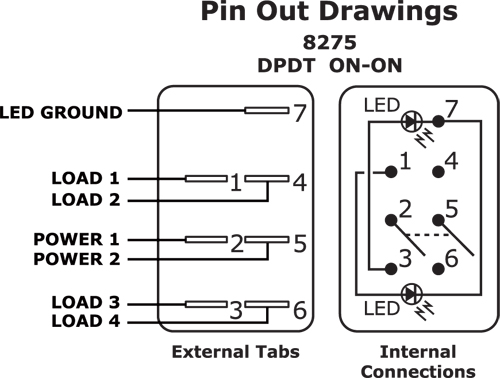
Here is a diagram of how the nav/ANC switch was wired....

For clarification if you can't tell,

Hot wire is connected to post 5
Nav and instrument lights to post 6
Grd to post 7
ANC comes in to post 3, then is jumped to post 8, then post 8 is jumped to post 1

I understand basic wiring but don't understand how this switch works (on off on, with 8 posts)

When I run my multitester from my 12v pos lead my nav light or ANC light lead I get a closed circuit, and the switch is in the off or either on position

Can anybody tell me the proper way this switch should be wired??

Another note- I don't know how this relates, but while I was testing the other leads in my wiring harness I noticed that if I connect the sender wire for my broken fuel gauge to the nav/ ANC wires or just about any other wire present, I get about 200/300 ohms resistance, but it's not showing an open circuit??? I don't fully understand how the sender works... Could this be one of my short problems?


Sent from my iPhone using Tapatalk


Sent from my iPhone using Tapatalk
 

Attachments

  • ImageUploadedByTapatalk1327183114.469368.jpg
    ImageUploadedByTapatalk1327183114.469368.jpg
    28.3 KB · Views: 0

NYBo

Admiral
Joined
Oct 23, 2008
Messages
7,107
Re: Nav switch wiring problem! Help

Welcome to iboats!:cool:

Unless the switch is lighted, there shouldn't be a "ground" connection at all. My advice would be to ditch the current switch completely and replace it with with an on-off-on SPDT or DPDT switch wired as follows (diagrams courtesy of Silvertip):
Nav-AnchorSwitch.jpg

NavSwitchWiring.jpg
 

Silvertip

Supreme Mariner
Joined
Sep 22, 2003
Messages
28,771
Re: Nav switch wiring problem! Help

One thing at a time:

1) The swtich wiring you show has no chance of working. Look at the diagram below and you will figure out why. The center pair of terminals on each side need to be jumpered together as well as from one side to the other. Then follow my diagram.
2) Is this a "lighted" switch (meaning does it have an indicator built into it? If not -- there should be no ground wire whatsoever on the switch.
3) Use the diagam below as a guide. Yes it is a six terminal switch. Treat the two center sets of contacts on your switch the same way the center contacts are on the diagram. In other words -- jumper them together.

NavSwitchWiring.jpg


4) Regarding the fuel gauge. You must not hook the pink sender wire to a +12 volt source. That wire goes to the "S" terminal on the gauge.
5) To measure sender resistance you disconnect the pink wire at the sender and then measure resistance between the threaded post and the metal shell of the sender. Depending on how much fuel is in the tank, resistance will be 33 ohms (about) when full, 109 ohms (about) when half full, and 240 ohms (about) when empty. (Hint: the only "open circuit" measurement with an ohm meter is "infinity")

Here is a diagram for the fuel gauge system -- again! Yup - using the "Search" feature would turn this up many times along with troubleshooting.

Gauge-SenderWiring.jpg
 

Pbguy420

Cadet
Joined
Jan 15, 2012
Messages
22
I did search, and everyone only talks about 3 or 6 pole switches, this one has 8...

Pretty sure it's the one that came on the boat originally. It matches everything else. It's obviously wired wrong tho...
Here's some pictures


Sent from my iPhone using Tapatalk
 

Pbguy420

Cadet
Joined
Jan 15, 2012
Messages
22
Here's the pics


Sent from my iPhone using Tapatalk
 

Attachments

  • ImageUploadedByTapatalk1327187906.686288.jpg
    ImageUploadedByTapatalk1327187906.686288.jpg
    42.3 KB · Views: 0
  • ImageUploadedByTapatalk1327187945.811888.jpg
    ImageUploadedByTapatalk1327187945.811888.jpg
    35.7 KB · Views: 0
  • ImageUploadedByTapatalk1327188108.923038.jpg
    ImageUploadedByTapatalk1327188108.923038.jpg
    40.8 KB · Views: 0
  • ImageUploadedByTapatalk1327188135.909893.jpg
    ImageUploadedByTapatalk1327188135.909893.jpg
    36.2 KB · Views: 0

NYBo

Admiral
Joined
Oct 23, 2008
Messages
7,107
Re: Nav switch wiring problem! Help

Here ya go:
Contura switches

Judging from your pix, I would say that the two terminals on the far right in pic #1 are for the internal light. If you verify that, wire the other six as per the diagrams we've posted above.
 

Pbguy420

Cadet
Joined
Jan 15, 2012
Messages
22
Well I got it working using the 6 pole diagram as above. Now before, and on all other switches a ground runs thru the number 7 - Btm right of pic one. I reconnected it.... That should be fine right? I know the nav get theyre ground elsewhere... But is it worth taking the time to remove or can I leave it? Will it cause me any shorting issues


Sent from my iPhone using Tapatalk
 

Don S

Honorary Moderator Emeritus
Joined
Aug 31, 2004
Messages
62,321
Re: Nav switch wiring problem! Help

I would guess that you have two grounds for the LED lights in the rocker. Which would give you 8 terminals instead of 7. This is probably the wiring diagram.

8275.jpg
 

Pbguy420

Cadet
Joined
Jan 15, 2012
Messages
22
Thx don s I'm pretty sure that's the one... I'll try it out today when I finally get this wiring nightmare finished


Sent from my iPhone using Tapatalk
 
Top