still wont fire 73 chrysler 85hp outboard

tommythecat

Cadet
Joined
Jul 21, 2018
Messages
27
i have a no spark issue not getting any spark to any of the three cylinders why? if i take off the regulator to test it does anyone know what the numbers should be? what ohms or voltage or resistance for a multimeter? my magnapower ignition is nice and green on the back side so it looks to be good no discoloration on it anywhere. should i pull my flywheel and test the stator or ? if so do you know where to find the ohms chat for it also? i am getting so frustrated it ran so well and the whole family is ready to use it. i did have to cut the trim harness three wires to get the motor off to repair the transom would this matter? i filed my points it did nothing. still no spark. i dont have the eye sensor in the distributor only points and no condenser anywhere that i can find. but there is a huge capacitor whats that for opposite side of the motor from the magnapower box. im stuck and need some help if anyone knows please?
 

jerryjerry05

Supreme Mariner
Joined
May 7, 2008
Messages
18,118
A second post for the same problem?
Can make things confusing.
Try outboardignitiondotcom for test procedures for the components.
For the more advanced tests you'll need
DVA attachment or a Peak Reading Volt Meter.
The simple tests can be done with an analog meter.(some use a digital, I never had good results with one)
  1. Disconnect all kill wires AT THE PACK.
  2. Check for broken or bare wires on the unit, stator and trigger.
  3. Measure DVA voltage of the stator between the output wire sets. With everything connected, reading should be approximately 180 volts or more. Resistance readings between the stator wire sets ranges from 680— 800 ohms.
  4. Disconnect the rectifier. If the engine fires, replace the rectifier.
And a pretty looking part doesn't mean it's good.

The trim has nothing to do with spark.

Some boats have a fuse panel under the dash.
Check the fuses there???
 

tommythecat

Cadet
Joined
Jul 21, 2018
Messages
27
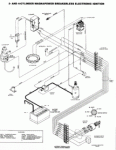
so here is a diagram of my wiring. i need to know what wire is the stop wire? and do i unhook all the regulator wires or just the red to test for fire? wiring_Chrysler_4cyl_Motorola.jpg
 

tommythecat

Cadet
Joined
Jul 21, 2018
Messages
27
another almost identical but no capacitor in this one i can see. whats it for? Chry3_4CylMagBreakerless.gif as there is no condenser next to my points would the big capacitor take this place?
 

jerryjerry05

Supreme Mariner
Joined
May 7, 2008
Messages
18,118
I think the white is the kill.
I can't access Outboardignition.com today??
They might have instructions for your system.
 

tommythecat

Cadet
Joined
Jul 21, 2018
Messages
27
white is the tachometer blue is the ignition , white/black is the signal wire to the distributor points. so remove the tach wire and disconnect the red wire only from the regulator and see if it sparks? is this right?
 

jerryjerry05

Supreme Mariner
Joined
May 7, 2008
Messages
18,118
Nordin can't post for some reason..
I volunteered to pass along his reply's on certain posts.
He said this about this post:

The belt driven battery CD ignition with distributer is really simple to troubleshoot.

The only thing that can go bad is the preamp (if it has one) or the CD module. Ignition coil can go bad, but they almost last very long time.

You check the CD module by scratching the white/black wire from module to dist. to ground.

If it sparks it is good, no spark …bad.

If you not connect a plug to HT wire from ign.coil you have to set the engine in TDC #1 plug (top).

Then you can have an issue in the dist.cap.


/Niklas
 

jerryjerry05

Supreme Mariner
Joined
May 7, 2008
Messages
18,118
Also from Nordin

That issue is 99% the CD module.


You can check the CD module if you know you have a good ignition coil.

Power at module, key in I position, pull the HT wire from dist. cap and put a spark plug at HT wire.

Ground the plug and loose the white/black wire from dist.

Then scratch the white/black wire to good ground.

If the plug sparks the CD module is good/working, if not it is bad.

Scratching the white/black wire to ground is the same as open and close the points.”
 

tommythecat

Cadet
Joined
Jul 21, 2018
Messages
27
just to be clear i am suppose to put the key on the run position and pull the number 1 plug and put it in the end of the number 1 plug wire then ground it like putting a wire around the threads to a engine ground. then scratch the white/black wire on a engine ground and watch the spark plug end for spark? and be sure the flywheel is at top dead center is this right? if so i did the test so not right i will go redo it .
 

tommythecat

Cadet
Joined
Jul 21, 2018
Messages
27
Resistance readings between the stator wire sets ranges from 680— 800 ohms. mine reads 1.0 - 1.1 it is over a bit so is that bad should i get a new stator? does this mean its bad? and another dumb question when i am at top dead center should the points be open or closed?
 
Last edited:

jerryjerry05

Supreme Mariner
Joined
May 7, 2008
Messages
18,118
More from Nordin:


You can test the CD module in different ways.

If you disconnect the HT wire that goes from ignition coil to dist.cap and connect the plug right there you isolate the issue to the CD module and ignition coil and you do not need to set the top cyl. in TDC.


If you test with #1 plug out but still connected to the dist.cap HT wire #1 plug, you have to set the top cyl. at TDC because you have to know the rotor in the dist. is pointing at #1 plug.

And you still do not know if it is an issue in the distr. cap!

The carbone pointer pin in the cap can be bad or bad connection to the rotor.


I do not think there is a problem with the stator. As the stator in this battery driven CD system only charge the battery.

It has nothing to do with the ignition system primarily. Yes if it does not charge the battery, then the ignition system will stop to work.

If the voltage goes down to 9,5-10V then the system stops to work.


Bets regards

Niklas
 

tommythecat

Cadet
Joined
Jul 21, 2018
Messages
27
ok so my new key switch and cdi unit came yea! but now i have a issue, the new cdi says it does not have a tach wire so am i still able to use this unit? does the tach wire tell the cdi when to fire as i dont have the sensor just points old fashion points no condenser and no electric eye sensor.
 

tommythecat

Cadet
Joined
Jul 21, 2018
Messages
27
More from Nordin:


You can test the CD module in different ways.

If you disconnect the HT wire that goes from ignition coil to dist.cap and connect the plug right there you isolate the issue to the CD module and ignition coil and you do not need to set the top cyl. in TDC.


If you test with #1 plug out but still connected to the dist.cap HT wire #1 plug, you have to set the top cyl. at TDC because you have to know the rotor in the dist. is pointing at #1 plug.

And you still do not know if it is an issue in the distr. cap!

The carbone pointer pin in the cap can be bad or bad connection to the rotor.


I do not think there is a problem with the stator. As the stator in this battery driven CD system only charge the battery.

It has nothing to do with the ignition system primarily. Yes if it does not charge the battery, then the ignition system will stop to work.

If the voltage goes down to 9,5-10V then the system stops to work.


Bets regards

Niklas

not sure i replied correctly so again here
ok so my new key switch and cdi unit came yea! but now i have a issue, the new cdi says it does not have a tach wire so am i still able to use this unit? does the tach wire tell the cdi when to fire as i dont have the sensor just points old fashion points no condenser and no electric eye sensor. ps. the new cdi say to hook the old tach wire to the regulator but which wire would it go on in this case please? 4 wires my choices are positive, negative, or one of the 2 a/c, a/c wires on it.
 

jerryjerry05

Supreme Mariner
Joined
May 7, 2008
Messages
18,118
Nordin sent this.


I will give a try to explain.


“Well for the first the CDI 155-3301 does not have a tach wire, soo you are not able to use your OEM tach.

The white wire from the old CD module does nothing to the ignition system.

It is only a signal wire for the tach.

Leave the white wire from your tach to the terminal board at the engine.


If you have the early Motorola Magnapower CD module that does not have a red wire just a blue one you connect as follow.


115-3301 Magnapower

Black (ground) Ground (if it is mounted with rubber studs) at block.

Blue 12VDC Blue (ignition at terminal board)

Gray (positive at ign.coil )

White/black Points at distributer or preamp (if it has the electronic dist.)


If you have the later Motorola Magnapower I CD module with a red wire, just unhook the old CD and leave the red terminal where the red wire was connected at terminal board unhooked.


I will try to give some information about the battery CD system. This old style CD system use the battery power to charge the CD.

The CD replaces the capacitor (condenser) in a regular ign. system and the points is the trigger for the CD to fire.

When the points open it gives signal to the CD to fire. If the distributer has an preamp (electrice eye) it replaces the points.

It is important that the alternator/stator is working and charging the battery, if not the engine will stop when the battery voltage goes lower then about 10V. The CD system drains the battery.

Also important that the battery voltage not goes lower then 9,5-10V when cranking at start. If it does, the engine will not start or will have trouble to start.


New CD system uses the stator (normaly 2 or 3 stators, 1 or 2 for ignition and 1 for battery charging) ) under the flywheel to charge the CD.


If you have a condenser (a large one) mounted at the engine then, it is for radio interferenc suppression.”
 

tommythecat

Cadet
Joined
Jul 21, 2018
Messages
27
wow that clears up so much for me. i am heading out to install the new one now that i understand everything. thank you! now lets hope this was the issue and it fixes the boat.
 

tommythecat

Cadet
Joined
Jul 21, 2018
Messages
27
good news i have spark! yea. ok so now i tested i have spark but my center lead wire is too short so i was wondering if i can use todays normal 7mm suppressor plug wire or does it need to be the same copper core?
 

jerryjerry05

Supreme Mariner
Joined
May 7, 2008
Messages
18,118
Yes you can use it.
Run it after dark and see if there is any plug wires arching/arcing/ jumping spark :)
 

tommythecat

Cadet
Joined
Jul 21, 2018
Messages
27
well i found a good wire from barron motor supply and made it myself. it works great, we took it out and it ran and idles great. but i put it in gear and it dies before i can give it any throttle. so i started it in gear lol it worked i tested it and it ran up the river then i pulled it out and checked the lower unit gear oil to be safe. well it was good i did the oil is white! so wheres it getting water? i see a shift shaft bushing and i can't find any other place it could get in? can i get the shift shaft bushing still?
 
Top