FishhawkNWO
Cadet
- Joined
- Jun 11, 2022
- Messages
- 9
I had posted this question in another thread but figured instead of hijacking that one that I would start a new one here. Thank you to those that already offered inputs on the topic.
If anyone has a tach they would like to sell please keep me in mind.
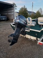
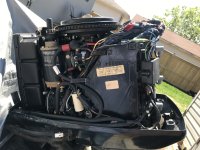
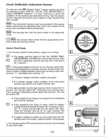
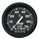
I purchased a boat last summer and started it for the first time yesterday after sitting all winter. It has a 1996 evinrude 50hp. The tach has system check with the 4 warnings.
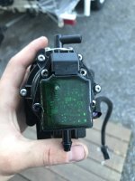
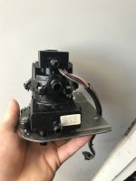
My first concern was that I wasn’t getting a “beep” when the ignition was turned on which lead me to find that the tach wasnt working. The tach was unplugged. While plugged in the motor would not start. With it disconnected it ran fine. After plugging it in again the tach got so hot it melted pin 1 and it pulled out from the gauge when I went to remove the connector.
After checking voltage on the harness side with the ignition in the on position there is 12V being supplied to pins 1,4, and 8. Previous owner said he didn’t know anything about it.
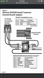
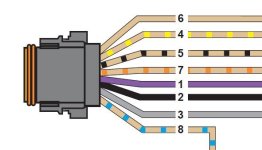
A member already explained which each pin does thanks @Chris1956
“Pin 1 is purple wire, should have ign +12VDC
Pin 2 is black wire, ground all the time
Pin 3 is grey wire, is tach sender
Pin 4 is tan/yellow from VRO pump, should not have voltage. Should ground to indicate "no Oil" alarm
Pin 5 tan/black is low oil in reservoir. Will ground when low oil.
Pin 6 -Tan- is overheat, Will be grounded when engine overheats.
Pin 7 is tan/orange. Is "system Check" alarm. indicates fuel restriction on V6 OBs only.
Pin 8 is tan/purple, will supply voltage to horn. Probably if you fix pin 4, that will get fixed.
So I would look for melted wires near VRO pump, allowing purple to short to tan/yellow”
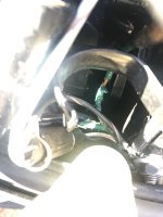
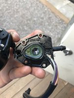
I followed the wiring and found where it connects to the VRO pump in the motor. There are no spots that I was able to find where the tan/yellow wire would be in contact with the purple wire.
A few questions:
1. Why would the tach stop the boat from being started?
2. Are there any other areas that might be giving 12V input to pin 4?
3. What would cause pin 1 to get so hot? (Although the entire tachometer got warm and is probably smoked now)
Was so excited to take my family out for a boat ride and this stuff happens. Tis life.
Thanks in advance.
- FishhawkNWO
If anyone has a tach they would like to sell please keep me in mind.
I purchased a boat last summer and started it for the first time yesterday after sitting all winter. It has a 1996 evinrude 50hp. The tach has system check with the 4 warnings.
My first concern was that I wasn’t getting a “beep” when the ignition was turned on which lead me to find that the tach wasnt working. The tach was unplugged. While plugged in the motor would not start. With it disconnected it ran fine. After plugging it in again the tach got so hot it melted pin 1 and it pulled out from the gauge when I went to remove the connector.
After checking voltage on the harness side with the ignition in the on position there is 12V being supplied to pins 1,4, and 8. Previous owner said he didn’t know anything about it.
A member already explained which each pin does thanks @Chris1956
“Pin 1 is purple wire, should have ign +12VDC
Pin 2 is black wire, ground all the time
Pin 3 is grey wire, is tach sender
Pin 4 is tan/yellow from VRO pump, should not have voltage. Should ground to indicate "no Oil" alarm
Pin 5 tan/black is low oil in reservoir. Will ground when low oil.
Pin 6 -Tan- is overheat, Will be grounded when engine overheats.
Pin 7 is tan/orange. Is "system Check" alarm. indicates fuel restriction on V6 OBs only.
Pin 8 is tan/purple, will supply voltage to horn. Probably if you fix pin 4, that will get fixed.
So I would look for melted wires near VRO pump, allowing purple to short to tan/yellow”
I followed the wiring and found where it connects to the VRO pump in the motor. There are no spots that I was able to find where the tan/yellow wire would be in contact with the purple wire.
A few questions:
1. Why would the tach stop the boat from being started?
2. Are there any other areas that might be giving 12V input to pin 4?
3. What would cause pin 1 to get so hot? (Although the entire tachometer got warm and is probably smoked now)
Was so excited to take my family out for a boat ride and this stuff happens. Tis life.
Thanks in advance.
- FishhawkNWO
Attachments
-
 5E0FBD9A-E302-435D-B029-A3819EF39FBC.jpeg1.6 MB · Views: 10
 -
 689DABBC-BBF4-4490-AA7E-5B8815F5CB8D.png1.9 MB · Views: 9
 -
 FA3F9E45-CE91-4DD3-87F3-E410BB5F94C5.jpeg30.6 KB · Views: 10
 -
 1BB68F49-0323-490C-B4AF-B858EBBDB32C.png429.8 KB · Views: 13
 -
 F5FE16C4-3B60-4AD3-9EA5-220B0F403A39.jpeg570.3 KB · Views: 11
 -
 A7CF7C7A-1111-4801-82DD-ACC5C9281826.jpeg1.1 MB · Views: 12