Aha! That goes back to my question in post #2. Why does that 1969 Big Twin have a big red plug? That is the wrong hookup. Not that it can't be made to work if you know a bit about electrical circuits.
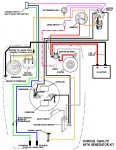
Nevertheless, here is what is needed for the switches to kill the motor. If you look at the bottom of the mag plate under the flywheel, you will see two spark wires coming out and going to the spark plugs. You will also see two smaller black wires coming out. Those two small wires are the kill wires. One of them needs to go forward to your ignition switch's "M" terminal. The second small wire first goes to the center of the vacuum cut-out switch, then from there also goes forward to the other "M' terminal on the ignition switch. I don't care what color the plug or wires are, just so there are two wires getting there as I described. If it is wired that way, the ignition switch will kill the motor.
Then of course, if you also want your new kill switch to work, wire it according to how I already told you.