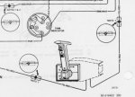
Voltmeter wiring: would this work?

Silvertip

Supreme Mariner
Joined
Sep 22, 2003
Messages
28,771
Re: Voltmeter wiring: would this work?

You aren't stirring up trouble. Trouble is when we get to 59 posts and installation of an ignition switch is still not complete because information must be dragged out bit by bit. If there are no dangling wires from the control box, you have two choices in my view. 1) Using a test light or voltmeter, check for +12 volts and ground at the engine end of the wires in the various harnesses. When you find them, open the harness sheath and make a splice at the control box end of that cable. or 2) Simply run a pair of wires from the engine bay or battery to the separate switch (momentary or SPST). On the other hand, if there are dangling wires from the control box, those were intended to power gauges and they will have a +12 volt and ground lead with the +12 volt lead being active only when the key is on. If the control box has a three terminal plug below the key switch, that's a tach connection and it too has +12 volt and ground connections as well as the tach sense signal.
 

axeslinger1957

Petty Officer 2nd Class
Joined
Aug 28, 2008
Messages
157
Re: Voltmeter wiring: would this work?

You aren't stirring up trouble. Trouble is when we get to 59 posts and installation of an ignition switch is still not complete because information must be dragged out bit by bit. If there are no dangling wires from the control box, you have two choices in my view. 1) Using a test light or voltmeter, check for +12 volts and ground at the engine end of the wires in the various harnesses. When you find them, open the harness sheath and make a splice at the control box end of that cable. or 2) Simply run a pair of wires from the engine bay or battery to the separate switch (momentary or SPST). On the other hand, if there are dangling wires from the control box, those were intended to power gauges and they will have a +12 volt and ground lead with the +12 volt lead being active only when the key is on. If the control box has a three terminal plug below the key switch, that's a tach connection and it too has +12 volt and ground connections as well as the tach sense signal.

I am going to go with option 2) using a dash-mounted SPST switch until after the big camping trip. I will then carefully perform surgery on the control box. One more compound question, if I may, and then I promise not to ask any more in this thread? First, I can just implement this with those little clips across the battery I want to monitor (red to pos, black to ground), right? Second, would I need a fuse? My gut tells me no, but I want to be safe. Real safe.
 

flargin

Chief Petty Officer
Joined
Aug 13, 2008
Messages
540
Re: Voltmeter wiring: would this work?

Thanks for telling us it was a PowerPort. not that I have a clue what one looks like, but I found this link.. I also think this is an outboard.

If you can get to the purple wire, it is your switched. It looks like there is a connector where the choke is attached. If you cannot get to the inside, then you can find your purple wire and tap into it.

Since this is your main power for your boat, I don't recommend using an auto "wire tap", I think it leads to too many "my boat stops once and a while.
ttp2.jpg


If you cut the line in the middle, Crimp and solder on a couple of eye connectors,
rv1-8.gif

and use a small bolt & nut to link the now 3 wires ( from ignition; to engine; to Voltmeter) together. this, and a little bit of water protection(grease) and tape or shrink tube, will help ensure you don't die in the middle of the lake.
 

axeslinger1957

Petty Officer 2nd Class
Joined
Aug 28, 2008
Messages
157
Re: Voltmeter wiring: would this work?

Thanks, Flargin. Yes, I have a 1978 Evinrude 70HP outboard. And, thanks to this fine forum, I found that wiring diagram last week. My concern now is safely opening the freeking Power Pilot without losing any parts, temper or nerve.
 

flargin

Chief Petty Officer
Joined
Aug 13, 2008
Messages
540
Re: Voltmeter wiring: would this work?

If I were you, and you are worried about not being able to re-assemble your controller, I would take and splice it into your line. do it close to the Control so you don't forget it, but far enough away, if you need to re-attach :)

here is my mercruiser manual, which shows the eyes and nut/bolt solutions, so it is SOP, which typically means it will last.

good luck

let us know how it goes.
 

Attachments

  • Mercruiser electrical note 1 picture.jpg
    Mercruiser electrical note 1 picture.jpg
    16.1 KB · Views: 0

Ridemywideglide

Petty Officer 2nd Class
Joined
Jan 13, 2009
Messages
166
Re: Voltmeter wiring: would this work?

I've got the eye-nut-bolt solution in the sensor wires to the pyro on my cummins...

I would disagree that it will last, tho it may be SOP. Even with heatshrink, I have to disassemble mine about twice a year and clean or the pyro starts getting intermittent.

IMHO, I'd cut the wire your looking to splice into, slide on some heatshrink, and solder the now 3 of them, all together, and cinch up the heatshrink.

An intermittent failure in your main ignition wire could get you someplace you don't want to be.
 

ScottinAZ

Master Chief Petty Officer
Joined
Jun 25, 2009
Messages
831
Re: Voltmeter wiring: would this work?

getting into the power pilot console is easy (just did this with mine)

1) remove decorative cover from top of console
2) remove the throttle handle
3) remove 2 screws from the back side (gunwale) of the top of the power pilot
4) remove 3 screws from the front (throttle) bottom side of the console
5) carefully remove the covers.

The spring is a detent for the throttle handle, so as long as that isnt disturbed, you shouldnt have an issue. all you need to do to access the switch is remove the covers, all else can stay put. As for the three cables, one is throttle control, another is shift, and the third bundle is all your wiring coming in from the engine housing.
 

axeslinger1957

Petty Officer 2nd Class
Joined
Aug 28, 2008
Messages
157
Re: Power Pilot -- HUGE GRATITUDE!

Re: Power Pilot -- HUGE GRATITUDE!

getting into the power pilot console is easy (just did this with mine)

1) remove decorative cover from top of console
2) remove the throttle handle
3) remove 2 screws from the back side (gunwale) of the top of the power pilot
4) remove 3 screws from the front (throttle) bottom side of the console
5) carefully remove the covers.

The spring is a detent for the throttle handle, so as long as that isnt disturbed, you shouldnt have an issue. all you need to do to access the switch is remove the covers, all else can stay put. As for the three cables, one is throttle control, another is shift, and the third bundle is all your wiring coming in from the engine housing.

THANK YOU, THANK YOU, THANK YOU!!!!!!!!!!!!!!!!!!!! :D
 
Top