Re: Homework is finished...
Re: Homework is finished...
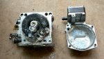
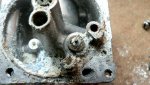
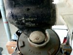
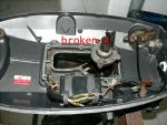
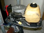
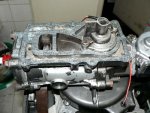
After making, placing a thicker gasket and cutting broken head crank case's border to be even, sealed the upper unit back on, took advantage that the head was disassembled turned it up side down and filled with pure vinegar both cylinder head water instakes, let them soak for one hour, placed a nozzle on one w.intake connected to a hose and to house water line, opened the faucett, and all salt remains popped out, no need to change head gasket as the old one seems in excellent condition. While engine continued to be up side down sprayed a generous amount of power tuner into cylinder, piston & rings let soak for 1 hour, wiped with old toothbrush and rinsed with fresh gasoline. Now has better punch when pulling rope than before.
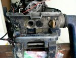
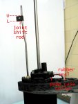
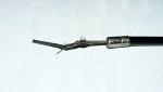
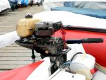
One dangerous issue found on older engines is that throttle cable is heavily rubbing against the bracket border that holds the wire cover into the assy, due to constant rubbing the threads of the wire tends to break and unroll from wire, when going near 3/4 or wot and backing throttle backward to slow down, the unrolled wire jams agains internal wire cover that is not smooth and locks the cable inside. Although the trottle grip seems to be backed, in crude reality the cable is still stuck inside cover at engine speed to which it was locked. The carb spring does not have the sufficient force to back throttle carb arm to it's resting position to slow down.
2 days a go a not experinced boater with a Mercury same model engine experimented a cable jam condition as explained and smashed against a pier at speed. Years back had the same problem with a Mariner, fortunately for me, the problem was detected at a close inspection and the bracket modified. It's just a matter of filing with a round file the bracket middle portion that rubs agains cable, once done, grease it with teflon grease.
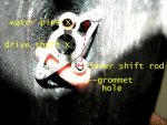
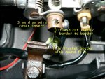
When assembling/disassembling the trottle cable and securing the extreme with the screw provided, tightening metal against metal will deteriorate cutting the cable fast, one way to minimize this issue is to place the plastic cover of a 3 mm electric wire inside the barrel that holds the cable with a screw, flash cut evenly upper & lower borders, pass the cable and tight screw as usual. A good idea would be to solder the extreme of the cable so that wire doesn't unwrap from main cable package. Keep wire cover constantly lubricated for smooth operation. If someone suspects is experimenting rubbing issues, check with magnifying glass. Check pic for fast and reliable modification.
Happy Boating


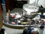
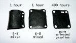
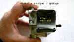
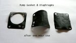
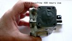
 not to mention gaskets, diaphragm, all are worn.