Wiring a 3-wire killswitch

TBarCYa

Senior Chief Petty Officer
Joined
Apr 13, 2005
Messages
781
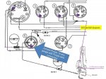
I'm rewiring my helm and think I've figured out the killswitch but before I actually do it, I was hoping to find a wiring diagram but haven't had any luck so I'm hoping someone here can let me know if I'm on the right path.

What I have is the key switch that has 3 wires, power, ignition and start. The killswitch also has 3 wires, purple (ignition), black/white and black. When the switch is ON it connects purple to blk/wht. When the switch is OFF it connects blk/wht to blk.

My thinking is that the ignition wire from the key goes to the normal ignition circuits to power the dash and the purple on the killswitch is connected to the same ignition from the key. Black on the killswitch goes to ground and the blk/wht goes to the ignition wire feeding the engine. This way, the dash is always on regardless of the killswitch and the ignition wire at the engine goes to ground to kill the engine when the lanyard is removed.

Does this sound right? I know just disconnecting the ignition wire going to the engine should kill the engine but grounding the ignition wire is also an acceptable method, but why doesn't the key ground the ignition wire?
 

alldodge

Moderator
Staff member
Joined
Mar 8, 2009
Messages
42,699
I'm assuming your working on a Mercruiser and not an Outboard
The kill switch breaks the connection of the purple wire. The purple wire powers everything, and the switch just breaks this connecction. The pic below shows how to bypass the kill switch

Kill Switch.jpg
 

TBarCYa

Senior Chief Petty Officer
Joined
Apr 13, 2005
Messages
781
It is a Mercruiser and not an outboard. What I don't like about that diagram is that the killswitch also kills the gauges which includes the battery and trim gauges and that it's a 2 wire killswitch that can only break the ignition circuit whereas mine is a 3-wire that I believe is meant to ground the ignition wire going to the engine.
 

GA_Boater

Honorary Moderator Emeritus
Joined
May 24, 2011
Messages
49,038
Do you know the purpose of a kill switch? Who cares if the gauges are disabled when the operator is tossed overboard, hopefully while wearing a PFD?
 

TBarCYa

Senior Chief Petty Officer
Joined
Apr 13, 2005
Messages
781
I guess 32,000 posts entitles you to be condescending to people asking legitimate questions... Maybe that's how you get to be a moderator around here.

Have you ever pulled the killswitch lanyard by accident? Ever turned to talk to someone with it clipped to your PFD and yanked it just a little too hard? Ever had to turn around to check your surroundings before making a turn? I have and it's good to know the battery condition and the trim position when the engine dies because it's not always obvious why you suddenly went from a running engine to a not running engine.
 

GA_Boater

Honorary Moderator Emeritus
Joined
May 24, 2011
Messages
49,038
Sorry bud, a bit testy today?

Let me answer your question, which I skipped over - My bad. "But why doesn't the key ground the ignition wire?"

Because you have a universal kill switch, made to work with I/O's and outboards. The answer to your question is you don't have a ground when the switch is closed because the black wire isn't wired to a ground source. If you ground the ignition through the kill switch, fuses will be popped because the ignition power is grounded, so that's not good.

My thinking is that the ignition wire from the key goes to the normal ignition circuits to power the dash and the purple on the killswitch is connected to the same ignition from the key.

This is where you're going wrong. The key switch in "On" supplies power through the kill switch to the ignition and instruments, as it is wired in series, not parallel. That's why the gauges are killed also.

To keep the gauges alive, the power feed needs to be before the kill switch so the kill switch only opens power to the ignition. But this defeats the kill switch. A switched power feed from the key switch to the instruments needs to be used instead of the power through the kill switch.

How short is your lanyard? Maybe a longer one is in order or relocating the kill switch?

BTW - I felt the tug, but that's just me.
 

TBarCYa

Senior Chief Petty Officer
Joined
Apr 13, 2005
Messages
781
Sorry bud, a bit testy today?

No. But I obviously know the purpose of a kill switch or I wouldn't be asking the proper way to wire it.

Because you have a universal kill switch, made to work with I/O's and outboards. The answer to your question is you don't have a ground when the switch is closed because the black wire isn't wired to a ground source. If you ground the ignition through the kill switch, fuses will be popped because the ignition power is grounded, so that's not good.

That's why I'm expecting to ground the ignition wire going to the engine, and not the ignition wire from the switch. The center terminal (common) goes out to the engine, the ON terminal goes to the ignition wire from the key and the OFF terminal goes to ground. So when the switch is OFF, nothing is connected to the ON terminal and the common is connected to the OFF terminal, or grounded. The only way I can think of that this will ground the ignition wire from the key is if there's a failure in the switch. Keep in mind that the ignition wire in the harness going to the engine is fed when the key connects +12v to the ignition terminal and is not fed from the engine.

This is where you're going wrong. The key switch in "On" supplies power through the kill switch to the ignition and instruments, as it is wired in series, not parallel. That's why the gauges are killed also.

So if looking at the diagram above, I'm going to move the kill switch from between the key and the gauges to that purple wire heading off to the right after the gauges... As that's the one that should be feeding the ignition system on the engine.

To keep the gauges alive, the power feed needs to be before the kill switch so the kill switch only opens power to the ignition. But this defeats the kill switch. A switched power feed from the key switch to the instruments needs to be used instead of the power through the kill switch.

It wouldn't defeat the kill switch because it would still open the ignition circuit which kills power to the ignition system.

How short is your lanyard? Maybe a longer one is in order or relocating the kill switch?

BTW - I felt the tug, but that's just me.

On the Maxum it's about 12" when tightly coiled, the Seadoo is 18" and is older and much more loosely coiled and this boat currently has one that's old and worn out but will be replaced so it's more like the Maxum.
 

Scott Danforth

Grumpy Vintage Moderator still playing with boats
Staff member
Joined
Jul 23, 2011
Messages
50,426
generic kill switches have a common terminal, a normally open terminal and a normally closed terminal.

on an I/O, you use the common terminal and the normally open terminal (the lanyard holds it closed)
on an outboard, you use the common terminal and the normally closed terminal (the lanyard holds it open)
 

GA_Boater

Honorary Moderator Emeritus
Joined
May 24, 2011
Messages
49,038
It wouldn't defeat the kill switch because it would still open the ignition circuit which kills power to the ignition system.

Not without rewiring the power feed to the gauges because the power would be fed backwards to the purple wire, which is the ignition and gauge power. The ignition and gauges need to be on separate power circuits to keep the gauges active if the lanyard is pulled.

To keep things simple, you could wire the voltmeter from the ignition switch "on" position and remove the purple wire from the voltmeter. Key on and the voltmeter shows voltage regardless of the kill switch open or closed.

You don't want to put a ground on the ignition purple wire when the lanyard is pulled because it will short 12 volts to ground with the key on and blow fuses.
 

alldodge

Moderator
Staff member
Joined
Mar 8, 2009
Messages
42,699
The pic in post 2 shows a SPST switch, just like a light switch. The lanyard goes behind the ON side, so when the lanyard comes out, it opens the circuit. This is a single purpose switch for I/O and IB.

You don't want to put a ground on the ignition purple wire when the lanyard is pulled because it will short 12 volts to ground with the key on and blow fuses.

Maybe it was the first response but this is the case. IT will hurt nothing to connect the 3rd terminal to ground other then blowing the 20 amp ignition fuse. Suggest not doing this but its not my boat

I/O and IB need power to run, so needs to be NC when running and NO when the lanyard is pulled
OB need NO when running and NC when lanyard is pulled to ground the magneto to kill the motor

The universal kill switches have the ability to place the lanyard in two positions, just need to fit it in the place that works NC for running
 

TBarCYa

Senior Chief Petty Officer
Joined
Apr 13, 2005
Messages
781
Maybe this will help clear up what I'm trying to do. Since I am rewiring the whole boat rewiring the gauges directly to the ignition terminal on the key is not a big deal. Also, I am using a kill switch that has NO and NC and since it never connects the IGN feed from the dash/key (NC) to ground (NO), it only connects the IGN to engine (COM) to ground (NO), there's no way it will blow the ignition fuse unless the switch fails and connects the NO and NC terminals.
 

Attachments

  • photo289457.jpg
    photo289457.jpg
    119.4 KB · Views: 1

alldodge

Moderator
Staff member
Joined
Mar 8, 2009
Messages
42,699
As I see it, in short, your breaking the 12V after the gauges instead of before the gauges. So the kill switch will remove 12V to the motor but not the gauges.

it only connects the IGN to engine (COM) to ground (NO), there's no way it will blow the ignition fuse unless the switch fails and connects the NO and NC terminals.

This is the only thing I don't understand. If the purple connects between the NO and COM there will be no 12V to the motor. It needs to connect between the NC and COM, so when pulled, it opens the circuit and removing 12V to the motor

no.jpg
 

TBarCYa

Senior Chief Petty Officer
Joined
Apr 13, 2005
Messages
781
Flip it around and ground the NO terminal. If you put motor on the left and gauges on the right of your drawing, it works exactly the same when NC but can ground the motor (to kill the ignition) without blowing the ignition fuse.

I get that grounding the ignition on the engine isn't required with a 4-stroke I/O engine but if it ever happens that I need that kill switch, I want to be 100% certain that it's going to work.
 
Top