New and in need of some advice: 40HP Johnson Electramatic

dmwelch

Seaman
Joined
Nov 7, 2016
Messages
62
Don't think that will work.-----You need a carburetor bowl that will fit a 40 hp.----Inspect those pistons first before thinking of spending a single $

I will,

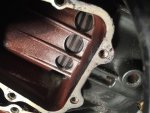
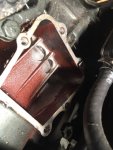
three questions: When I take off the bypass covers, wont I only be able to see one side of the pistons? How do i inspect the other side, is there bypass covers on each side?

Did this engine originally have a fuse box? If so what was the location?

Also I see that the wiring loom has a connector for main electrics up to dash, where was that connection point? in the engine cover or somewhere else?

Thanks Guys
 

racerone

Supreme Mariner
Joined
Dec 28, 2013
Messages
38,793
You will only be able to see the one side of the pistons.------------This is a " little money spent " inspection step.-----It often tells the story.
 

jimmbo

Supreme Mariner
Joined
May 24, 2004
Messages
13,831
If there is scuffing/scoring on the intake side of the piston, the side opposite is usually much worse
In about 1965 OMC eliminated the Junction Box and moved the components to places under the cowl
The wiring diagram doesn't show a fuse
 
Last edited:

F_R

Supreme Mariner
Joined
Jul 7, 2006
Messages
28,226
What do I need to get the carbs back to original?
If they did what I suspect they did, just replace the carburetor's float bowl with the correct one. Be sure you have the correct high speed jet (orifice plug) in it, and use new gaskets.

OMC's original attempt at an automatic choke on the 40 was heated by hot water from the cooking system. Well, some say they worked, but nearly all worked very poorly. Then in 1964, they did away with the hot water choke and came out with the one you have. It is heated by hot air coming from the exhaust cover. Also has an electric booster solenoid for cold start-up. It is way better than that old hot water choke.
 

F_R

Supreme Mariner
Joined
Jul 7, 2006
Messages
28,226
Looking at the bigger picture, they might have installed the adjustable needle because it was running too rich on the fixed jet. And it may have been running too rich because they plugged the choke hot-air stove. That blocked off a certain amount of air going to the intake manifold. People don't consider the consequences of their re-engineering genius. Just speculating.
 

F_R

Supreme Mariner
Joined
Jul 7, 2006
Messages
28,226
Another thing that will make it run really, really rich is leaving out the o-ring that goes on top of the water pump housing and/or the spacer for the drive shaft isolation tube (if long shaft). Leave those parts out and it will choke to death on it's own exhaust gasses.
 

dmwelch

Seaman
Joined
Nov 7, 2016
Messages
62
You will only be able to see the one side of the pistons.------------This is a " little money spent " inspection step.-----It often tells the story.

Alright I took the bypass covers off and was surprised to find the piston rings and still springy and the piston didn't looked scored etc, see attached pictures. Let me know what you guys think.

Side Question: Should I re-install a fuse box for the electrical system?
 

Attachments

  • IMG_2141_zps3mepryja.jpg
    IMG_2141_zps3mepryja.jpg
    240.8 KB · Views: 1
  • IMG_2140_zpsjga8fgq1.jpg
    IMG_2140_zpsjga8fgq1.jpg
    211 KB · Views: 1

F_R

Supreme Mariner
Joined
Jul 7, 2006
Messages
28,226
What I can see looks very good. I think you have a keeper.

Reinstall a junction box?? Heck no. Getting rid of that troublesome thing was one of the best things they ever did.
 

jimmbo

Supreme Mariner
Joined
May 24, 2004
Messages
13,831
What I can see looks very good. I think you have a keeper.

Reinstall a junction box?? Heck no. Getting rid of that troublesome thing was one of the best things they ever did.

Hear Hear!
 

racerone

Supreme Mariner
Joined
Dec 28, 2013
Messages
38,793
Pistons look good.--------------Next step is to check whether lower unit shifts properly.----apply 12 volts to green lead and see if prop drags one way and locks up the other way.----Repeat with blue wire.
 

dmwelch

Seaman
Joined
Nov 7, 2016
Messages
62
You guys are the best!

Pistons look good.--------------Next step is to check whether lower unit shifts properly.----apply 12 volts to green lead and see if prop drags one way and locks up the other way.----Repeat with blue wire.

Racerone, I'll try that tonight and see what happens and report back thanks for the help with the next steps!

Separate question: the original key Starter Switch on the wiring diagram has 5 leads Batt, Ign, Ass, Starter and lead going off to cut off switch (is this a constant 12v? what is the point of this?), now I have different on with 3 lead (Batt, Ign and Starter) can I make this work?

Thanks
 

racerone

Supreme Mariner
Joined
Dec 28, 2013
Messages
38,793
You need to be very carefull with wiring and switches !--------This motor does not use the battery to make the spark for the plugs.------You need a switch with 2 M terminals on it.---------Do not apply 12 volts to the coils.--------One other step is to remove the flywheel to inspect the coils.-------You may find 2 cracked coils if the motor has sat for 20 years.------------We often find that 2 new coils have been installed already.--------Pictures always help.
 

dmwelch

Seaman
Joined
Nov 7, 2016
Messages
62
You need to be very carefull with wiring and switches !--------This motor does not use the battery to make the spark for the plugs.------You need a switch with 2 M terminals on it.---------Do not apply 12 volts to the coils.--------One other step is to remove the flywheel to inspect the coils.-------You may find 2 cracked coils if the motor has sat for 20 years.------------We often find that 2 new coils have been installed already.--------Pictures always help.


So you think I'd better off just buying a new switch from marineengines.com to be safe?

Removing the flywheel seems easy enough, the flat screw on the sides and the top should just pop up right?
 

racerone

Supreme Mariner
Joined
Dec 28, 2013
Messages
38,793
??----Removing the flywheel can be a challenge for a novice.--Remove the recoil.----Remove the three 1/4" bolts-----Remove the nut 1-1/16" socket---Then use a puller with 3 bolts thread size is 1/4-20.-----A hammer may be required.---Do not try to improvize with any other style puller.
 

dmwelch

Seaman
Joined
Nov 7, 2016
Messages
62
??----Removing the flywheel can be a challenge for a novice.--Remove the recoil.----Remove the three 1/4" bolts-----Remove the nut 1-1/16" socket---Then use a puller with 3 bolts thread size is 1/4-20.-----A hammer may be required.---Do not try to improvize with any other style puller.

I'm making a trip to Harbor Freight this evening to pick up a puller.

When I inspect the coils, what should I be looking for? Burnt marks missing wire connections? Will I be able to notice if they are cracked?

Also should I adjust the points etc while I've got the flywheel off?
 

dmwelch

Seaman
Joined
Nov 7, 2016
Messages
62
An entire carb from a post 63 40hp, the method of link-and-sync changed in 1964, so 61-63 carb might not adjust properly. That said you might currently be using a 1960 carb(only year the 40hp had adjustable high speed) or an older 35hp carb, or even a mid 60s 33hp carb. Or your carb is original and had an older fuel bowl swapped to it


Another method would be a fuel bowl from a 1961 or later carb

http://www.boatinfo.no/lib/evinrude/...rude.html#/100 Hot air choke carb like yours 1964 - 1970

http://www.boatinfo.no/lib/evinrude/...rude.html#/102 Older adjustable carb(pre1960 engines and mid 1960s 33hp), and a water heated choke-1960 -1963 40hp

Jimmbo,

Would this float bowl fit, I grabbed the same part number from the marinesengine.com and popped it in ebay and this came up with matching number?

Thanks
 

jimmbo

Supreme Mariner
Joined
May 24, 2004
Messages
13,831
An image would be helpful. Reading your post, I will assume you got a part number for a 40 hp float bowl, ran the number on eBay and had a hit
 

F_R

Supreme Mariner
Joined
Jul 7, 2006
Messages
28,226
You guys are the best!


Racerone, I'll try that tonight and see what happens and report back thanks for the help with the next steps!

Separate question: the original key Starter Switch on the wiring diagram has 5 leads Batt, Ign, ***, Starter and lead going off to cut off switch (is this a constant 12v? what is the point of this?), now I have different on with 3 lead (Batt, Ign and Starter) can I make this work?

Thanks


Did you look at the wiring diagram supplied in post #5? It clearly shows what is required for an ignition switch. Yes, 5 terminals and they are all used.

iboats has them, no need to go off to their competitor. They are supplying this free forum.
 

dmwelch

Seaman
Joined
Nov 7, 2016
Messages
62
Did you look at the wiring diagram supplied in post #5? It clearly shows what is required for an ignition switch. Yes, 5 terminals and they are all used.

iboats has them, no need to go off to their competitor. They are supplying this free forum.

Didn't know they sold things sorry I'll be happy to check into that
 

dmwelch

Seaman
Joined
Nov 7, 2016
Messages
62
Pistons look good.--------------Next step is to check whether lower unit shifts properly.----apply 12 volts to green lead and see if prop drags one way and locks up the other way.----Repeat with blue wire.

Applied 12 volts to both forward and reverse clutch and definitely work!
 
Top