Re: 50hp force no spark top cylinder
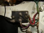
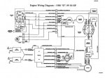
check this out..I'm very sure is the CDI.. or switch box ..is the way mercury and force call them.....bud do your checks first...I think your will the the #16 in the list
Force Troubleshooting
Prestolite ADI Ignitions 1984-1992
General
1. Check for broken wires and terminals, especially inside the plastic plug-in connectors. We recommend that you remove the
pins from the connectors using the CDI 511-9706 pin removal tool and visually inspect them.
2. Check the flywheel for a broken or loose magnet.
3. Disconnect the stop wires from the CD and connect a DC voltmeter between the stop wires and engine ground, turn the
ignition switch on and off several times. If, at any time, you see voltage appearing on the meter, there is a problem in the
harness or ignition switch. At NO TIME SHOULD YOU SEE BATTERY VOLTAGE ON A STOP CIRCUIT.
4. Visually inspect stator for burned or discolored areas. If found, replace the stator. If the areas are on the battery charge
windings, it indicates a possible problem with the rectifier.
IF THERE IS NO SPARK ON ANY CYLINDER:
1. Disconnect the stop wire AT THE PACK.
2. Check for broken or bare wires on the CD Module, stator and trigger.
3. Check the stator resistance and output using the CDI meter with the 511-9773 peak reading adapter and 511-9770 piercing
probes, as follows:
Read Form Read To Resistance (OEM) Resistance (CDI) DVA (connected) DVA (disconnected)
Yellow Blue 680-850 250-350 180V or more 200 V or more
Yellow Engine Gnd Open Open 180 V or more (a) 2 V or less (b)
Blue Engine Gnd Open Open 180 V or more (a) 2 V or less (b)
NOTE: Remember that the stator may use Brown/Yellow or Brown/Black/Yellow for Yellow and Brown/Blue or
Brown/Black/Blue for Blue.
(a) The DVA reading to engine ground is checking a circuit inside the power pack. If the readings are not fairly equal, swap the stator
wires going to the power pack and recheck. If the low reading stays on the same wire from the stator, replace the stator. Otherwise,
replace the power pack.
(b) Most meters will pick up a small amount of voltage due to inductive pick-up. As long as the voltage is very low, it will not indicate a
problem.
4. Disconnect the rectifier. If the engine now has spark, replace the rectifier.
NO SPARK OR INTERMITTENT SPARK ON ONE CYLINDER:
1. Check the stator and trigger resistance; the trigger wire sets should read approximately 50 ohms between the wire sets
(DVA-.5V or more), the stator should read 680-800 ohms (factory) and 250-350 ohms (CDI/RAPAIR) DVA 180V or more
from blue to yellow.
2. If readings are good, disconnect stop wire from one pack. If the dead cylinder starts sparking, the problem is likely the
blocking diode in the opposite pack.
NO FIRE ON TWO CYLINDERS:
1. If two cylinders from the same CD unit will not fire, the problem is usually in the stator. Test per above.
2. If the engine has a CDI stator installed:
a. If #1 and #3 are the ones not firing, disconnect the Yellow stator wire from the # 1 pack and see if the #3 cylinder
starts firing. Is so, replace the #1 pack. If not, then reconnect the Yellow stator wire to the # 1 pack and
disconnect the Yellow stator wire from the # 2 pack and see if the #1 cylinder starts firing. If so, replace the # 2
pack.
b. If #2 and #4 are the ones not firing, disconnect the Blue stator wire from the # 1 pack and see if the #4 cylinder
starts firing. Is so, replace the #1 pack. If not, then reconnect the Blue stator wire to the # 1 pack and disconnect
the Blue stator wire from the # 2 pack and see if the #2 cylinder starts firing. If so, replace the # 2 pack.
ENGINE WILL NOT SHUT OFF:
Check the stop circuit in the pack by using a jumper wire connected to the stop wire coming out of the pack and shorting it to
ground. If this stops the pack from sparking, the stop circuit in the harness or on the boat is bad, the ignition switch could also be
bad.
COILS ONLY HAVE SPARK WITH THE SPARK PLUGS OUT:
Check for dragging starter or low battery causing slow cranking speed. DVA test stator and trigger.
HIGH SPEED MISS:
1. Using the CDI meter with the 511-9773 peak reading adapter, (or CD-77) and 511-9770 piercing probes, DVA check stator
voltage to each pack at high speed. If it exceeds 400 volts, replace the pack.
2. Disconnect the rectifier. If the engine now has spark, replace the rectifier.
16
Two Cylinder Engines using Combination CD Module with Built-in Ignition Coils (1984-88)
NO SPARK OR INTERMITTENT SPARK ON ONE CYLINDER:
1. Check the Brown kill wires. They MUST be separated from each other. THIS SYSTEM SHORTS THE BROWN WIRES
TOGETHER TO KILL THE ENGINE. The common practice of connecting the kill wires together and shorting them to
ground in order to stop the engine will not work on this engine. Disconnect the Brown kill wires and retest. If you have
spark, check the ignition switch?s ?M? terminals if using remote start. You should have a White wire on one terminal and a
Blue wire on the other terminal. If both the Blue and White wires are connected together, correct the wiring. If the engine
has a tiller handle, check the push button stop switch.
2. Check the stator resistance; you should read 680-800 ohms (factory) and 250-350 ohms (CDI) DVA 180V or more from
blue to yellow (Note ? On some two cylinder engines, the stator has two blue wires and no yellow wire. The stator will read
from blue to blue). All stator wires should read open to engine ground.
3. Disconnect and check the trigger resistance; trigger wire sets read approximately 50 ohms between the wire sets (DVA-0.5V
or more), and open to engine ground.
4. If readings are good, disconnect stop wire from one pack. If the dead cylinder starts sparking, the problem is likely the
blocking diode in the opposite pack.
ENGINE WILL NOT SHUT OFF:
Check the stop circuit in the pack by using a jumper wire connected to the stop wire coming out of the pack and shorting it to
ground. If this stops the pack from firing, the stop circuit in the harness or on the boat is bad. The ignition switch could also be
bad.
17
Force Troubleshooting
Prestolite ADI Ignitions 1984-1992
Two Cylinder Engines Using Separate Switch Boxes and Ignition Coils
GENERAL:
1. Disconnect the stop wires from the CD and connect a DC voltmeter between the stop wires and engine ground, turn the
ignition switch on and off several times. If, at any time, you see voltage appearing on the meter, there is a problem in the
harness or ignition switch. At NO TIME SHOULD YOU SEE BATTERY VOLTAGE ON A STOP CIRCUIT.
2. Check the flywheel for a broken or loose magnet.
3. Check for broken wires and terminals, especially inside the plastic plug-in connectors. We recommend that you remove the
pins from the connectors using the CDI 511-9706 pin removal tool and visually inspect them.
4. Visually inspect the stator for burned or discolored areas. If found, replace the stator. If the areas are on the battery charge
windings, it indicates a possible problem with the rectifier.
IF THERE IS NO SPARK ON EITHER CYLINDER:
1. Disconnect all stop wires AT THE PACK.
2. Check for broken or bare wires on the switch box, stator and trigger.
3. Using the CDI meter with the 511-9773 peak reading adapter, or CD-77 and 511-9770 piercing probes, measure DVA
voltage of the stator between the output wire sets. With everything connected, reading s should be approximately 180 volts
or more. Resistance readings between the stator wire sets range from 680 ? 800 ohms (factory) and 250-350 ohms
(CDI/RAPAIR).
4. Disconnect the rectifier. If the engine now has spark, replace the rectifier.
IF THERE IS NO SPARK OR INTERMITTENT SPARK ON ONE CYLINDER:
1. Check the stator resistance; you should read 680-800 ohms (factory) and 250-350 ohms (CDI/RAPAIR) DVA 180V or more
from blue to yellow (Note ? On some two cylinder engines, the stator has two blue wires and no yellow wire. The stator will
read from blue to blue). All stator wires should read open to engine ground.
2. Check the trigger resistance, trigger wire sets read approximately 50 ohms between the wire sets (DVA-0.5V or more), and
open to engine ground.
3. If readings are good, swap the power pack output from the ignition coil that works to the one that does not. If the coil that
had spark stops sparking, replace the power pack.
ENGINE WILL NOT SHUT OFF:
Check the stop circuit in the pack by using a jumper wire connected to the white stop wire coming out of the pack and shorting it
to ground. If this stops all spark from the pack, the stop circuit in the harness or on the boat is bad. The ignition switch could also
be bad.
NO SPARK UNLESS THE SPARK PLUGS ARE OUT:
Check for dragging starter or low battery causing slow cranking speed. DVA test stator and trigger.
HIGH SPEED MISS:
1. Using the CDI meter with the 511-9773 peak reading adapter, (or CD-77) and 511-9770 piercing probes, DVA check stator
voltage to each pack at high speed. If it exceeds 400 volts, replace the pack.
2. Disconnect the rectifier. If the engine now has spark, replace the rectifier.
3. Check for broken wires and terminals, especially inside the plastic plug-in connectors. We recommend that you remove the
pins from the connectors using the CDI 511-9706 pin removal tool and visually inspect them.
4. Check the flywheel for a broken or loose magnet.
5. Disconnect the stop wires from the CD and connect a DC voltmeter between the stop wires and engine ground, turn the
ignition switch on and off several times. If, at any time, you see voltage appearing on the meter, there is a problem in the
harness or ignition switch. At NO TIME SHOULD YOU SEE BATTERY VOLTAGE ON A STOP CIRCUIT.
6. Visually inspect the stator for burned or discolored areas. If found, replace the stator. If the areas are on the battery charge
windings, it indicates a possible problem with the rectifier.
Connections Color Code Cross Reference
Pack #1 (Firing #1 and #2 Cylinders) FUNCTION OLD NEW
Pack: White/Orange Stripe Trigger: White/Orange Stripe Trigger Orange White/Orange Stripe
White/Yellow White/Yellow (a) Trigger Green White/Yellow Stripe
White/Red White/Red (a) Trigger Red White/Red Stripe
White/Green Stripe White/Green Stripe Trigger White/Green Stripe White/Green Stripe
Pack: Brown/Yellow Stripe Stator: Brown/Yellow Stripe Stator Blue Brown/Blue Stripe
Brown/Blue Stripe Brown/Blue Stripe Stator Yellow Brown/Yellow Stripe
Pack: Orange/Blue Coil: White Ignition Coil White Orange/Blue
Blue/Red White Stop Circuit White Black/Yellow
18


