AQ131 Questions (Spark Issues)

yspecv

Cadet
Joined
Apr 28, 2025
Messages
8
Hello All. New to the forum. I have a few questions and looking for insight.

Boat: Glastron Sierra w/ VP AQ131

Pulled it out this year and ran into spark issues. Got it fired up once and started to miss fire after 10-15 minutes. Proceeded to clean points, cap, and rotor, as well as check spark plugs and wires. Ended up ordering a replacement set of wires as the ones that were there were original and quite crispy. After cleaning everything, the engine would fire but wouldn't start. After more diagnostics, I determined that both my batteries were bad, due to the fact that I would drop well below 10v while cranking (which were suspect last year, even though I made it through the season) so I replaced both. I also found a crack in my distributor cap, so a new tune up kit was ordered.

Now, this is where I need help:

While waiting for my new cap to come in, I was checking the points to ensure there was spark. To my dismay, there was none while opening the points. I then verified that there was 12v at the distributor (purple wire), which there was. I pulled the coil to verify OHMs and had zero across the primary and 9ish on the secondary. I am in need of an aftermarket part number for a coil that I can purchase from a local auto parts store. From everything I've read, they are an internally resisted 3 ohm coil. I have searched and can not find an external ballist resistor in my engine, which is why I tend to agree.

Also, while messing with everything, I noticed that while the purple wire was connected to the distributor, my voltage on my volt gauge would drop to about 11.5v. If I disconnected the wire, it would just back up to 12.3+. Anyone have any thoughts or is this a result of the bad coil?

P.S. I've done a few keyword searches of the forums and have not found any info related to my specific issues. Thanks.
 

alldodge

Moderator
Staff member
Joined
Mar 8, 2009
Messages
42,621
Welcome

while the purple wire was connected to the distributor, my voltage on my volt gauge would drop to about 11.5v. If I disconnected the wire, it would just back up to 12.3+
The ballast resistor is the wire it self and don't think there is anything wrong with your coil. Meters are hit/miss with their accuracy and it's hardly never the coil

You should have 2 wires on the plus side of the coil. When cranking it should get full 12V and once started the voltage should drop
 

yspecv

Cadet
Joined
Apr 28, 2025
Messages
8
Welcome


The ballast resistor is the wire it self and don't think there is anything wrong with your coil. Meters are hit/miss with their accuracy and it's hardly never the coil

You should have 2 wires on the plus side of the coil. When cranking it should get full 12V and once started the voltage should drop
There is only one wire on the positive side of the coil.
 

Bondo

Moderator
Staff member
Joined
Apr 17, 2002
Messages
71,103
There is only one wire on the positive side of the coil.
Ayuh,...... Welcome Aboard,...... Donno how Volvo deals with it, but there should be a 2nd wire that feeds 12v to the points, when starting,....
Merc uses a wire from the starter's solenoid,....
 

alldodge

Moderator
Staff member
Joined
Mar 8, 2009
Messages
42,621
There is only one wire on the positive side of the coil.
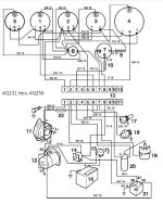
Looks like VP uses power from the key goes straight to coil when cranking and once started it comes from the ALT thru a ballast resistor item 22

So when the key is ON and not running power comes from both

AQ131 thru AQ250 wiring.jpg
 

Scott Danforth

Grumpy Vintage Moderator still playing with boats
Staff member
Joined
Jul 23, 2011
Messages
50,313
what did you set the dwell to? what is the dwell meter reading?
 

yspecv

Cadet
Joined
Apr 28, 2025
Messages
8
Update:

After some more troubleshooting today, I determined it was the points. Using the selocmarine manual, I conducted a bunch of diag. and traced it to the points. Replaced the points, cap, and rotor and she fired up and runs good. I gapped the points at .018" and I'll check the dwell when I get my meter tomorrow. But I am happy she's up and running.
 

kenny nunez

Captain
Joined
Jun 20, 2017
Messages
3,337
The wire diagram that AD posted is the genuine Volvo panel which does power the coil in cranking mode.
Make double sure that there is 12 volts to the coil when cranking. The reason I ask this is most boat builders do not use the genuine Volvo instrument panel and wire harness. The Volvo ignition switch has the ignition by pass circuit built into it. If your panel and harness are the generic marine style then your bypass circuit is not there.
There is a unused spade connector on the outboard side of the starter solenoid which is hot in cranking mode, make up a wire that will connect that spade to the extra spade on the + side of the coil and you will have a full 12 volts to the coil in cranking mode.
 

yspecv

Cadet
Joined
Apr 28, 2025
Messages
8
The wire diagram that AD posted is the genuine Volvo panel which does power the coil in cranking mode.
Make double sure that there is 12 volts to the coil when cranking. The reason I ask this is most boat builders do not use the genuine Volvo instrument panel and wire harness. The Volvo ignition switch has the ignition by pass circuit built into it. If your panel and harness are the generic marine style then your bypass circuit is not there.
There is a unused spade connector on the outboard side of the starter solenoid which is hot in cranking mode, make up a wire that will connect that spade to the extra spade on the + side of the coil and you will have a full 12 volts to the coil in cranking mode.
She is up and running as of now, but thanks for the info. I will check to see if this wire is there. There is a white wire that runs to the + now, but it disappears into the main wiring harness. I am assuming that it runs up to the instrument cluster.
 

ESGWheel

Chief Petty Officer
Joined
Aug 29, 2015
Messages
588
Here is more on what Kenny is referring to: it a 4 post Starter Solenoid (vs three – usure what you have). It may be a spade or a post with nut. This no. 4 terminal on the solenoid gets +12VDC only when the starter is engaged. See pic and this thread link for more info on how that all works.

4 Wire Solenoid.jpg
 

yspecv

Cadet
Joined
Apr 28, 2025
Messages
8
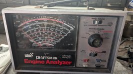
what did you set the dwell to? what is the dwell meter reading?
1000000408.jpg

I completely forgot that I had this analyzer. Hooked it up today and confirmed the dwell was 62⁰ at .018" points gap. I may try to run her again today to make sure everything is good. It ran good yesterday so fingers crossed 🤞
 

ESGWheel

Chief Petty Officer
Joined
Aug 29, 2015
Messages
588
Too funny. I had the same model I bought decades ago. Was one of the more expensive tools other than Snap-On torque wrench if I recall correctly. I only recently gave it to my son for his toolbox, still works great!
 

yspecv

Cadet
Joined
Apr 28, 2025
Messages
8
Too funny. I had the same model I bought decades ago. Was one of the more expensive tools other than Snap-On torque wrench if I recall correctly. I only recently gave it to my son for his toolbox, still works great!
👍 I think I bought mine at a rummage sale for $2. Only bought it as a display piece for my garage. I never thought I would actually use it.
 
Top