Force 507X8B Ignition

msstring

Petty Officer 3rd Class
Joined
Jun 6, 2014
Messages
85
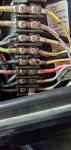
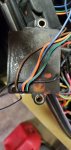
I replaced my 507X5A with this 507X8B that I bought used out of ebay. I wired it up per the colors but I wonder if something is different at the switch than my old motor. Two issues now: 1) Coils smoked badly and smell of smoke. 2) Motor started right up but would not shut down with the switch. Had only run for a few seconds so it died when I idled it down. This used motor was available because it slowed down after running at WOT for a short time. Said to maybe be a feul issue so didn't seem to be to big a problem.

So now what? Is this something with the wiring or was the original problem a coil issue? Both coils are distorted, one has fluid leaking out. To start, can anyone give me a listing of what I should expect to have with a test light or volt meter at each pin of terminal strip with key on and key off? Other suggestions? Guessing I'm going to need coils regardless, hopefully I haven't wrecked anything else. Compression is 118 PSI.
 

Attachments

  • photo340575.jpg
    photo340575.jpg
    1.3 MB · Views: 6
  • photo340576.jpg
    photo340576.jpg
    1.3 MB · Views: 5
  • photo340577.jpg
    photo340577.jpg
    1.3 MB · Views: 5
  • photo340578.jpg
    photo340578.jpg
    1.4 MB · Views: 5
Last edited:

msstring

Petty Officer 3rd Class
Joined
Jun 6, 2014
Messages
85
Motor is a 1988 50 HP Force. Does anyone have a wiring diagram for this motor.
 

Nordin

Commander
Joined
Jun 12, 2010
Messages
2,596
The 507X5A is a 1985 year model with battery ignition, the 507X8B is a 1988 with CDI ignition.
The battery ignition is feed by the battery, the CDI ignition is self energizing from magnets in the flywheel.
Your CDI system was only used in 1 or 2 years then there was a Prestolite CDI system on the 50Hp:s I believe.

I do not know where you can find a electrical diagram online, maybe some other jerryjerry or The Force etc will cime in and post a diagram.

However the different between battery system and CDI is that the blue wire and white wire are connected different.

Battery system
Blue......connected to I terminal at keyswitch and blue (ignition) at terminal strip at engine.
White......Not in use.

CDI system
Blue..... connected to M terminal at keyswitch and at blue terminal at engine. Then the blue terminal is grounded at engine.

White.......connected to M terminal (the other one, there are two at the switch) at keyswitch. and white terminal at engine.
This white then goes to the CDI module.

The big different in those two systems is that the battery system need 12VDC to operate and you stop the engine by shutting off the 12VDC voltage.
The CDI system is self energizing and it does not need 12VDC to operate. You stop the engine by grounding out the CDI module.
 
Last edited:

msstring

Petty Officer 3rd Class
Joined
Jun 6, 2014
Messages
85
Thanks!!! I have an old boat without a stop switch do I need that for the system to work? Or is that in parallel to the key switch?

Any thoughts on the CD Coil modules? Will they survive or are they toast?
 

Nordin

Commander
Joined
Jun 12, 2010
Messages
2,596
I think they are fried as you got 12VDC voltage at the stop circuit.
My experience from CDI systems that got power at the stop circuit is that they usually went bad.
But wire it up correct and give it a try, you have nothing to lose.
 
Last edited:

msstring

Petty Officer 3rd Class
Joined
Jun 6, 2014
Messages
85
Well spring is here so starting at my boat project again... last fall I fried one of the CDI units after wiring up the ignition switch wrong. Bought a replacement and tried to install it today. Original is no longer available so the replacement is from CDI Electronics. Not a direct replacement but they provided the attached instructions. But they are not very clear and my motor doesn't exactly match the wire colors. I'm hoping some of you can help be translate this. Instructions are in the pictures.

From the instructions for #2:
- Red on the motor should go to Green on the CDI
- I don't understand the next line. It would seem like the motor wire could be either green or white with green and it would go to orange on the CDI. This is how I wired it.
- I don't have a brown but do have a blue. So I am assuming that the Blue from the motor goes to the blue on the CDI.
- Brown on the motor appears to go to Brown on the CDI.
I have everything wired per my assumptions above but get no spark on the new CDI. But, I do have spark on the other one.
I then switched everything so the new CDI is wired per the same assumptions for #1. Same result, spark on the original CDI but not the new one. I then tested the kill wire by disconnecting it. Same result. Reconnected the kill wire and with the key off no spark on either unit and with the key on I again have spark on the old unit but not the new. It seems like it is down to the new CDI unit and I am hoping I just have something wired wrong. Suggestions?
The wires on the new unit, Brown is not showing
20210424_165450.jpg

This is before I started
20210424_165410.jpg

This is how I have it wired but no spark
In this picture I had disconnected the Brown as a test as noted above.
20210424_174654.jpg
 

Attachments

  • 20210424_165429.jpg
    20210424_165429.jpg
    2.2 MB · Views: 4
  • 20210424_210838.jpg
    20210424_210838.jpg
    1.5 MB · Views: 4

Nordin

Commander
Joined
Jun 12, 2010
Messages
2,596
I have looked at it closer and it seams like you have wired it correct.
So some questions then.
The brown wire at the new CDI box, where have you connect it and does the new CDI box have any black wire?
From the diagram in #4 by The Force the CDI box should have a ground wire (black) and the brown wire should be connected at the terminal for the harness to blue/black or blue. Maybe the new CDI box does not have a good grounding.
If you do not get any improvement I would suggest you to contact CDI Electronics and speak to a technician.
The new CDI box might be bad as it do not produce spark at cylinder #1 when you swap with that one.
The trigger signal for #2 cylinder seams to be okey as it produce spark with #1 CDI box when swapped.
 

msstring

Petty Officer 3rd Class
Joined
Jun 6, 2014
Messages
85
I have looked at it closer and it seams like you have wired it correct.
So some questions then.
The brown wire at the new CDI box, where have you connect it and does the new CDI box have any black wire?
From the diagram in #4 by The Force the CDI box should have a ground wire (black) and the brown wire should be connected at the terminal for the harness to blue/black or blue. Maybe the new CDI box does not have a good grounding.
If you do not get any improvement I would suggest you to contact CDI Electronics and speak to a technician.
The new CDI box might be bad as it do not produce spark at cylinder #1 when you swap with that one.
The trigger signal for #2 cylinder seams to be okey as it produce spark with #1 CDI box when swapped.
Thanks @Nordin ! The new CDI does have a black wire and that came already attached to a mounting plate for the CDI. That plate is fastened to the engine block so I would think it is grounded but I can certainly check it easy enough. Otherwise I'll reach out to CDI tech support.
 

msstring

Petty Officer 3rd Class
Joined
Jun 6, 2014
Messages
85
Thanks @Nordin ! The new CDI does have a black wire and that came already attached to a mounting plate for the CDI. That plate is fastened to the engine block so I would think it is grounded but I can certainly check it easy enough. Otherwise I'll reach out to CDI tech support.
I did reach out to CDI tech support. They were very helpful, I ended up sending my unit back and they sent me a different one. Motor now runs on both cylinders. But, now I have shift issues. I will start a new thread on that.
Thanks everyone for your help!
 
Top