ghost in the machine ?

alldodge

Moderator
Staff member
Joined
Mar 8, 2009
Messages
42,637
I buy the Duracell AGM bats from Sams club, and so far so good.

To test the coil, need to take all the wires off it
 

ab59

Ensign
Joined
May 10, 2017
Messages
979
I should have tried some epsom salts in the battery cells before I returned it but it just plain slipped my mind. I have saved the battery on my garden tractor two years ago and my wifes little Rav4 last year with that trick. Suffering a little slippage today I guess.
 

ab59

Ensign
Joined
May 10, 2017
Messages
979
Coil test---OK , I did disconnect the only remaining ground but I will make sure that I remove everything next time.
 

ab59

Ensign
Joined
May 10, 2017
Messages
979
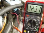
DSC02427.JPG

Note, when I tried to test the red wire I would get a reading of about 23 or 25 that would vanish and I could not get it back again.
None of this correlates to the testing material that I have been studying or I have misunderstood it. Again , battery is disconnected and all wires are disconnected from the coil at this point.
 

Attachments

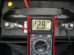
  • DSC02428.JPG
    DSC02428.JPG
    800.8 KB · Views: 0
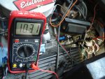
  • DSC02422.JPG
    DSC02422.JPG
    1.3 MB · Views: 0

alldodge

Moderator
Staff member
Joined
Mar 8, 2009
Messages
42,637
The coil gets tested using the ohm scale as in the link above.
Center post to - should be 6000 to 15000 ohms
From + to - should be .4 to 2 ohms

The battery when taken off a charger will be above 12.7 for a while. Another thing that can show higher then normal is the accuracy of the meter

Don't use ohms scale to measure voltage on the motor. Use ohm scale with power disconnected to check continuity of a single wire.

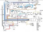
This should be your wiring
OMC Engine Wiring.jpg
 

ab59

Ensign
Joined
May 10, 2017
Messages
979
First diagram I have seen that has the correct color wires and is complete , it should help greatly . thank you ! About the Alternator wires , the splice specifically , it appears that the two wires ( purple and PU/RED ) are joined together at the splice so does it make a difference where they attach to the back of the Alternator ? The new alternator has a black and red wire and does not match the harness wires so I had connected the red wire to PU/RED and the PU to the black wire and it looks like that may be wrong by this diagram .
A forgotten Dr's appointment has come up so I'll be gone most of the day but will re test the coil and Alternator later when I return.
 

alldodge

Moderator
Staff member
Joined
Mar 8, 2009
Messages
42,637
Never have fully understood the splice, but I would keep the wire colors as shown. That is other then the diagram kind of shows the wires swapping, I would not do that. In fact if someone elase has actually spliced all the wires together, this can cause charging issues
 

ab59

Ensign
Joined
May 10, 2017
Messages
979
Have just completed another check on the coil and got these results --- with the meter set on OHMS ( dial set on 20k ) , all leads disconnected , battery disconnected I still get a 10.28 OHMS going from the center coil wire location to ground terminal on the coil. Going from the - terminal to the + terminal I get 000 , I tested several times making sure I had everything right and that is going by the book instructions so does this mean the coil is no good ? If so why would the engine start and run with a bad coil ?
 

alldodge

Moderator
Staff member
Joined
Mar 8, 2009
Messages
42,637
Yes, the coil is bad. It would run but not very well, and should have had a weak spark. The coil was burning up, and now is basically shot. The good thing, is you proved the coil is an issue, and at least don't cost that much
 

ab59

Ensign
Joined
May 10, 2017
Messages
979
I guess it's just one more thing that is wrong and needs to be replaced. This engine has a converted electronic ignition I think at least it has an electronic ignition anyway so would any 12 volt coil with 1.5 ohm resistance work for this or do I need a high output coil ? Any recommendations ?
 

alldodge

Moderator
Staff member
Joined
Mar 8, 2009
Messages
42,637
Get about any 12V coil, look for internal resistance, not external
 

ab59

Ensign
Joined
May 10, 2017
Messages
979
I'm looking at a Pertronix 45011 Flame thrower coil with .6 ohm resistance . I had read something today that made me think that this distributor needed a 1.5 ohm so now I'm not sure. Any thoughts ?
 

alldodge

Moderator
Staff member
Joined
Mar 8, 2009
Messages
42,637
The "flame thrower" sounds cool, but IMO its all hype. It will work and so will another coil from your local auto store.
 

ab59

Ensign
Joined
May 10, 2017
Messages
979
The Flame Thrower is what Pertronix sells with their ignition conversion kit so that is what I was going to do but instead I went to the local auto parts store and bought one similar and of coarse 20 bucks more . At least I did not have to wait for shipping and I can just install it this morning and see where I'm at on this thing.
Any possibility of the coil being the short problem ?
 

alldodge

Moderator
Staff member
Joined
Mar 8, 2009
Messages
42,637
bought one similar and of coarse 20 bucks more

Wow, can get one from advance auto for under $20

Either way, yes it is possible that the coil was causing the short. I'm only going by what your saying. You said across the + and - was zero and with that it would draw more current.
 

ab59

Ensign
Joined
May 10, 2017
Messages
979
New coil in but there's good news and bad news. Good news is the back of the key switch is only getting warm not hot. Bad news is that the fuel gauge still shows overfull and the alternator wires at the coil seem to be leaning towards the hot side but I may have the ignition and the sensor wires reversed . If the purple wire is the sensor wire then it is hooked up right.
Fuel gauge -- I went so far as to remove the sending unit ground at the tank and used a ground under the dash ( a bolt ) then ran a hot wire straight to the battery with the same results , tested both with the battery hooked up and not hooked up and with and without the ground at the battery and basically got the same results. . I am continuing to study how to trace the wiring short or ground fault but need to print out the instructions because I can't remember all the steps to chase this stuff down. I can't print anything for a few more days or I would just print it out.
I have spent most of the day digging through the wiring at the transom looking for some sign but have not discovered anything useful other that there have been many things abandon through the years but not too bad.
I have been using the info at boatinginfo.com under Troubleshooting basic DC Electrical Problems , trying to understand and use your advice and suggestions . It has helped but can't seem to get to the heart of the problems.
 

alldodge

Moderator
Staff member
Joined
Mar 8, 2009
Messages
42,637
If the purple wire is the sensor wire then it is hooked up right

NO

The purple wire is ignition 12V which powers up everything. Connecting this wire to anything other then 12V power causes shorts, increase current, everything going down hill.

I really want to help you fix this, but I don't see any way of being able to do this from a distance. You need some help by someone which understands basic electrical circuits
 

ab59

Ensign
Joined
May 10, 2017
Messages
979
Ok then, thanks for your help . I will pursue this on my own.
 

ab59

Ensign
Joined
May 10, 2017
Messages
979
too much conflicting information anyway as your own diagram shows PURPLE TO SENSOR
 
Top