Reed Fuel Sensor ?

gm280

Supreme Mariner
Joined
Jun 26, 2011
Messages
14,605
Hello everybody. I have a few questions concerning the typical reed fuel sensors. I think I understand how they actually work and even made a attempt to build one myself. I had some good ideas but bad executions it seem. My premise is that they take magnetic reed type switches and align them along the length of the tube in the fuel tank and as the float, with a magnet attached, floats up and down in the fuel tank, it turns on the appropriate reed switch to indicate the fuel level. Doesn't sound that complicated. But my feeble attempt to design one and make it operate seems to be flawed anyways. Here is what I designed and actually built.

Reed Fuel SensorSchematic.gif

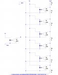
Since I was building this for a shallow tank (~8"), I wanted to get as many steps as I could for the sensor to display a much more accurate fuel level on the gauge. So here I designed 14 level steps with Reed switches. And to offer the most accurate fuel level each switch has to increase and/or decrease in resistive levels. So I took the total length and divided that up into 14 steps and used that number to divide into a full tank resistance reading. In this case ~15 ohms per step with the very top at 30 ohms.

Reed Fuel Sensor PC layout.gif

And this is the actual circuit board layout from that schematic design. You can see how I angled the reed switches to give me the most steps. And each step from the bottom up switches in another 15 ohm resistor to add up to the actual fuel level. Sound pretty good so far, doesn't it? :noidea:

IMG_0004.JPG
This is the actual PC board I designed and built. You can see the resistors and reed switches. And the old sealed cork float and rare Earth magnet as well. The entire circuit was to be installed in a standard 1/2" copper tube sealed both at top and bottom with the float and magnet siding on the outside of the tube. And as the fuel level rose or fell, the different reed switches would turn on and off indicating the fuel level. Still sound plausible doesn't it. That's what I thought as well.
IMG_0005.JPG
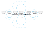
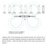
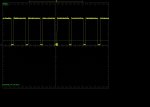
Still another picture of the final PC board. However, dummy me assembled the PC board with the reed switches and didn't take into account that the switches should have been installed on the PC board in the exact same configuration. Meaning all of them should have been facing the same way. But I didn't do that. I soldered them however I bend the leads to fit. And that created some questionable results. First of all, they responded to the magnet differently, I'm assuming because I didn't solder them the same way. Secondly the magnet seems to close or open multiple reed switches instead of a nice predictable step fashion. That could be the random soldering of the reed switches as well. But the magnet even turned on or off reed switch further away from the placement of the magnet and even skipped over some switches as well. And that wasn't taken into account. So every time I slid the magnet along the circuit, I never got the same stepped results...ever. So I have since abandoned this circuit now. But I wanted to show folks what I did and how I thought a typical reed fuel sensor worked. Has anybody ever taken one apart? I'd like to see their design. :noidea:
 

dingbat

Supreme Mariner
Joined
Nov 20, 2001
Messages
16,338
Why spend all the time and effort on something you can buy for $35?
 

gm280

Supreme Mariner
Joined
Jun 26, 2011
Messages
14,605
Why spend all the time and effort on something you can buy for $35?

dingbat, I know, but it is what I like to do. I like making things and thought it would be interesting to see how it worked. I will probably buy one but was just playing around with this circuit. Yes it is silly, but interesting all the same. :facepalm:
 

sam am I

Commander
Joined
Jun 26, 2013
Messages
2,169
dingbat, I know, but it is what I like to do. I like making things and thought it would be interesting to see how it worked. I will probably buy one but was just playing around with this circuit. Yes it is silly, but interesting all the same. :facepalm:

Don't sweat it gm!! Been there, DO that

To me I suppose and FWIW, It's not always about the money saved or the time spent, sure I have wasted a few pennies here and there, I'm not about just throwing money out the window either but, sometimes it's just about taking a little extra time or money, learning something new or old and perhaps (for sure) gaining deeper self understanding…..and sometimes just a hand to the forehand and say’n…. “doh”!!!! and have a good laugh. NO pennies lost and were ALL gained back IMO then.

Unfortunately I see more and more a country full of McD's instant gratification generations that just throw away, who DEMAND more and more, aren't willing to learn/do S**T and have entitlements attitudes who will someday be driving this buss....This is not good IMO and perhaps it will be (is) our downfall in the global market places.......Go India!!

geeesh, so sad these days………........Rant over.
 
Last edited:

gm280

Supreme Mariner
Joined
Jun 26, 2011
Messages
14,605
Ha, thanks Sam. Seems we do think alike on a lot of issues. I have always wanted to make things my entire life. And I have done that for a career for 40 plus years already. It isn't about saving money, but interested in making things myself. When I was younger, seems so many folks actually did that same thing. But seeing the latest generation coming along, they don't seem to have that inventive drive these days. But I won't get into that any further. I guess I will continue building things until I finally physically or mentality can't anymore. :thumb:
 

dingbat

Supreme Mariner
Joined
Nov 20, 2001
Messages
16,338
dingbat, I know, but it is what I like to do. I like making things and thought it would be interesting to see how it worked. I will probably buy one but was just playing around with this circuit. Yes it is silly, but interesting all the same. :facepalm:

If your at that point in life where you have the time to reinvent the wheel, more power to you. ;)

Guessing your sensors are too close together relative to the magnetic field your generating. Either change the spacing of the switches or narrow the magnetic field.

What is the sensing range of your switches?
 

gm280

Supreme Mariner
Joined
Jun 26, 2011
Messages
14,605
Actually dingbat, if I lay the reed switches out length to length, then I don't get the numbers to make it much worth making. The fuel gauge would jump from full to about 3/4, to 1/2, to 1/4 and so on. Being the short length for such a reed setup makes it iffy. So I guess I will have to go with a resistive swing arm type and deal with the sloshing in the tank, like everybody else. I even tried to use sensors like water sensors. But I can absolutely tell you gasoline does NOT conduct electricity in the least. Otherwise that would be the best setup. I should have known gas doesn't conduct because I recently changed a fuel pump in the tank and they sit in gas all day long without conducting current. It is how they work. So I am not trying to reinvent the wheel, but odd how simple inventions seem to come from people that do such things and learn things instead of simply using marketed products all the time. So many of todays useful products came from failed ideas that lead to some amazing inventions. You just never know what you will stumble on to. :thumb:
 

dingbat

Supreme Mariner
Joined
Nov 20, 2001
Messages
16,338
Unfortunately I see more and more a country full of McD's instant gratification generations that just throw away, who DEMAND more and more, aren't willing to learn/do S**T and have entitlements attitudes who will someday be driving this buss....This is not good IMO and perhaps it will be (is) our downfall in the global market places.......Go India!!

geeesh, so sad these days???........Rant over.
Speaking of global market place, I've covered three Continents and traveled more than 150K miles in the past 4 weeks to support manufacturing in this country.

No instant gratification. Long cycle Sales.
Yes, I'm demanding.
For being unwilling to learn or do anything, I get paid pretty well to travel the world convincing foreign companies to buy American made products
Do I fell entitled to my salary? You bet, given the effort and the number of jobs my position supports.
And yes, I have friends and customers in India as well...lol

Now perhaps you can see why some of us don't have the time nor desire to reinvent the wheel every time. ;)
 
Last edited:

sam am I

Commander
Joined
Jun 26, 2013
Messages
2,169
No Title

BTW, it's the magnetic lobes get'n ya. Perhaps place two magnets together with 80% 20% Nickle-Iron caps on each end

NiFe-NS-NS-NiFe where "NS" is a magnet and "-" is the boundaries between each materials

The 80 Nickle will shield/block/disperse the flux as best as possible of the outer lobes so as not to effect switches above and below while where the two magnets (NS-NS) meet the flux is concentrated/centralized to the intended switch it's next too.

Just guessing though :)
 

Attachments

  • photo232982.png
    photo232982.png
    8.7 KB · Views: 0
  • photo232983.jpg
    photo232983.jpg
    40.9 KB · Views: 1
Last edited:

sam am I

Commander
Joined
Jun 26, 2013
Messages
2,169
Speaking of global market place, I've covered three Continents and traveled more than 150K miles in the past 4 weeks to support manufacturing in this country.

No instant gratification. Long cycle Sales.
Yes, I'm demanding.
For being unwilling to learn or do anything, I get paid pretty well to travel the world convincing foreign companies to buy American made products
Do I fell entitled to my salary? You bet, given the effort and the number of jobs my position supports.
And yes, I have friends and customers in India as well...lol

Now perhaps you can see why some of us don't have the time nor desire to reinvent the wheel every time. ;)

Well then, if the shoe doesn't fit.......However, IMO learning/gaining knowledge about how a wheel works by experimenting isn't necessarily "re-inventing". Who knows, the man might come up with a even better mouse trap :) Ya never know, stranger things have happened.

BTW, you sound a little stressed, perhaps some down time? ;)
 
Last edited:

bruceb58

Supreme Mariner
Joined
Mar 5, 2006
Messages
30,590
So I guess I will have to go with a resistive swing arm type and deal with the sloshing in the tank, like everybody else.
Wema and Moeller both make these

There are capacitive senders too.
 
Last edited:

gm280

Supreme Mariner
Joined
Jun 26, 2011
Messages
14,605
Thanks Bruceb58, I did know they made them. Just trying my ideas and such. I am retired and have some extra time when not monkeying around with neighbor's repairs. I actually made this attempt about a year or so ago and was moving things around in the shop looking for other items and found it again. I have since moved on to more boat direct work now. But I still have a lot of neat circuitry that I've built that have worked for both the boat and vehicles.I like designing things and since I do have a loaded shop to basically make anything, I keep busy.
 

bruceb58

Supreme Mariner
Joined
Mar 5, 2006
Messages
30,590
I like doing circuits too so I understand.

Most gauges have a lot of hysteresis in them to act like a filter so sloshing usually doesn't show up on the gauge itself.

I tend to only do circuits which I can't find readily available to just buy.
 
Last edited:

sam am I

Commander
Joined
Jun 26, 2013
Messages
2,169
No Title

BTW, it's the magnetic lobes get'n ya. Perhaps place two magnets together with 80% 20% Nickle-Iron caps on each end

NiFe-NS-NS-NiFe where "NS" is a magnet and "-" is the boundaries between each materials

The 80 Nickle will shield/block/disperse the flux as best as possible of the outer lobes so as not to effect switches above and below while where the two magnets (NS-NS) meet the flux is concentrated/centralized to the intended switch it's next too.

Just guessing though :)

So being a self proclaimed mouse trap expert...........and pondering this of course with Starbucks in hand

http://custommagneticshielding.magne...ns-custom-spec

Place the two bonded ring magnets inside of an appropriate sized 80% Nickel cylinder''s.But place/use two nickel end cap?s(cups) butted and glued/secured together face to face such that they create a magnetically'ish sealed cylinder around the ring mag's (like snapping together and hiding the ring mag's inside a cylindrical plastic Easter egg shell). But, pre-drill/bore centered holes out of the end caps but just so your 1/2" copper pipe sides in and out/through mag/cap assembly. Mount float on outside perimeter of cap/mag assembly.

"And Now for Something Completely Different"


http://www.infineon.com/dgdl/Infineo...173f11d5a23c96


$1.00 ea. at digi-key, not sure what you paid for the reeds.


I'm current using a Uni-polar 4905 on a project with super mag's. The schmitt's et al hysteresis keep the lobes at bay(for me anyway, I'll post a scope plot in a bit as I have six individual mag's passing/rotating by one fixed hall. Same diff thou all with nice clean single edges as each of the mag's lead up and pass by the sensor). Thinking they'd preform well here gm. Not sure about what gas will do to them thou..........hmmm. I think they'd be fine though. Mine are potted in epoxy FWIW

I was lazy here drawing out your design, didn't want to draw the entire ladder out, but you get the jist i'm sure. The L1 ,Q1 sub circuit thing I draw'd up on the left represents the (lame rendition ) infineon's hall device. I just copy and pasted a hand full it into the ladder

Rainy day project eh? Never give up man!!!
 

Attachments

  • photo233057.jpg
    photo233057.jpg
    140.8 KB · Views: 0
Last edited:

sam am I

Commander
Joined
Jun 26, 2013
Messages
2,169
No Title

Nothing earth shattering to look at here, point being though there is just one transition per magnets as they pass by the 4905. No extra glitches in the wave forms if you will.

The design feeds this pulse train to a processor that is counting each transition which in turn is used for rotational positioning. It counts up and back in the 1000's of pulses. If I have even ONE extra, non-repeating pulse in it, that would create positional errors.........This doesn't happen.

GL gm
 

Attachments

  • photo233070.JPG
    photo233070.JPG
    110.5 KB · Views: 0
  • photo233071.JPG
    photo233071.JPG
    101.2 KB · Views: 0
Last edited:

gm280

Supreme Mariner
Joined
Jun 26, 2011
Messages
14,605
Well Sam, seems you are into this with great enthusiasm. I obviously don't understand magnetism flux capabilities as well as I should. I do understand what you are saying, but never to the point you seem to understand. Yes the side lobes were a huge part of the initial problem. I could see them (in effect) as I was raising and lowering the magnet around the reed switch PC board. And I knew right then it was the secondary side magnetic lobs causing the problems because it would turn on reed switches well above and below the ring magnet position. The adjacent reed switches seem to work pretty well. But the side lobs were awful.

I guess I could flip flop two ring magnets and see what happens. I have to ask, what O'scope are you using? I have a very old but extremely well built Techtronic 454 dual trace 150mz scope. And oddly enough, I actual have the designer's email address and have conversed with him a few times. He obviously has long since retired, but he told me of all the Techtronic equipment he designed, the 454 model was the best. Because there were no proprietary parts involved with that design. All the replacement part can be obtained at most any electronic store. He also said he has lots of 454 parts in his little shop as well.

Thanks for the additional info. I may get back to that little project and see what works with your additional ideas. :thumb:
 

sam am I

Commander
Joined
Jun 26, 2013
Messages
2,169
It's just a cheap-o digital wannabe tek. Fits on the dining room table next to my dinner plate nicely thou :facepalm: Sick, I know........DSO5062B.

And GL...... Nothing like a good bit of trying to figure something out., but you'll get it whipped.
 
Last edited:
Top