gm280
Supreme Mariner
- Joined
- Jun 26, 2011
- Messages
- 14,605
Hello everybody. I have a few questions concerning the typical reed fuel sensors. I think I understand how they actually work and even made a attempt to build one myself. I had some good ideas but bad executions it seem. My premise is that they take magnetic reed type switches and align them along the length of the tube in the fuel tank and as the float, with a magnet attached, floats up and down in the fuel tank, it turns on the appropriate reed switch to indicate the fuel level. Doesn't sound that complicated. But my feeble attempt to design one and make it operate seems to be flawed anyways. Here is what I designed and actually built.
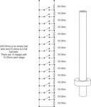
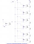
Since I was building this for a shallow tank (~8"), I wanted to get as many steps as I could for the sensor to display a much more accurate fuel level on the gauge. So here I designed 14 level steps with Reed switches. And to offer the most accurate fuel level each switch has to increase and/or decrease in resistive levels. So I took the total length and divided that up into 14 steps and used that number to divide into a full tank resistance reading. In this case ~15 ohms per step with the very top at 30 ohms.

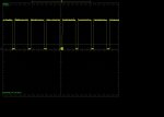
And this is the actual circuit board layout from that schematic design. You can see how I angled the reed switches to give me the most steps. And each step from the bottom up switches in another 15 ohm resistor to add up to the actual fuel level. Sound pretty good so far, doesn't it? :noidea:
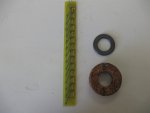
This is the actual PC board I designed and built. You can see the resistors and reed switches. And the old sealed cork float and rare Earth magnet as well. The entire circuit was to be installed in a standard 1/2" copper tube sealed both at top and bottom with the float and magnet siding on the outside of the tube. And as the fuel level rose or fell, the different reed switches would turn on and off indicating the fuel level. Still sound plausible doesn't it. That's what I thought as well.
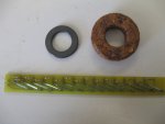
Still another picture of the final PC board. However, dummy me assembled the PC board with the reed switches and didn't take into account that the switches should have been installed on the PC board in the exact same configuration. Meaning all of them should have been facing the same way. But I didn't do that. I soldered them however I bend the leads to fit. And that created some questionable results. First of all, they responded to the magnet differently, I'm assuming because I didn't solder them the same way. Secondly the magnet seems to close or open multiple reed switches instead of a nice predictable step fashion. That could be the random soldering of the reed switches as well. But the magnet even turned on or off reed switch further away from the placement of the magnet and even skipped over some switches as well. And that wasn't taken into account. So every time I slid the magnet along the circuit, I never got the same stepped results...ever. So I have since abandoned this circuit now. But I wanted to show folks what I did and how I thought a typical reed fuel sensor worked. Has anybody ever taken one apart? I'd like to see their design. :noidea:

Since I was building this for a shallow tank (~8"), I wanted to get as many steps as I could for the sensor to display a much more accurate fuel level on the gauge. So here I designed 14 level steps with Reed switches. And to offer the most accurate fuel level each switch has to increase and/or decrease in resistive levels. So I took the total length and divided that up into 14 steps and used that number to divide into a full tank resistance reading. In this case ~15 ohms per step with the very top at 30 ohms.

And this is the actual circuit board layout from that schematic design. You can see how I angled the reed switches to give me the most steps. And each step from the bottom up switches in another 15 ohm resistor to add up to the actual fuel level. Sound pretty good so far, doesn't it? :noidea:

This is the actual PC board I designed and built. You can see the resistors and reed switches. And the old sealed cork float and rare Earth magnet as well. The entire circuit was to be installed in a standard 1/2" copper tube sealed both at top and bottom with the float and magnet siding on the outside of the tube. And as the fuel level rose or fell, the different reed switches would turn on and off indicating the fuel level. Still sound plausible doesn't it. That's what I thought as well.

Still another picture of the final PC board. However, dummy me assembled the PC board with the reed switches and didn't take into account that the switches should have been installed on the PC board in the exact same configuration. Meaning all of them should have been facing the same way. But I didn't do that. I soldered them however I bend the leads to fit. And that created some questionable results. First of all, they responded to the magnet differently, I'm assuming because I didn't solder them the same way. Secondly the magnet seems to close or open multiple reed switches instead of a nice predictable step fashion. That could be the random soldering of the reed switches as well. But the magnet even turned on or off reed switch further away from the placement of the magnet and even skipped over some switches as well. And that wasn't taken into account. So every time I slid the magnet along the circuit, I never got the same stepped results...ever. So I have since abandoned this circuit now. But I wanted to show folks what I did and how I thought a typical reed fuel sensor worked. Has anybody ever taken one apart? I'd like to see their design. :noidea:


