- Joined
- Jul 23, 2011
- Messages
- 52,228
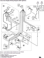
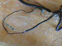
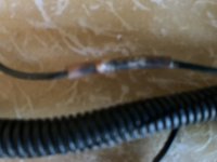
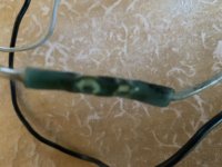
You mean the condenser on the points?what is the purpose of the filter that runs from the coil to the distibutor.
It is to prevent the points from burning up. In the stickies are a tutorial on points ignition. You will want to read them