Mercruiser Setting Timing on 3.0L

kd4pbs

Petty Officer 1st Class
Joined
Mar 5, 2012
Messages
298
If the head cracked - due to improper tightening sequence even when there is a gasket that is compressing - then it would have surely failed while in service. A huge thick hunk of cast iron is much more resilient than you might think. The gasket will have already been compressed, so there will be no issue. But if you feel more comfortable following a sequence, then there's no reason not to do so.
As far as the lifter preload, I'm referring to the valve lash (zero lash plus the 1/2 turn or so preload). What you do when setting the lash is actually put a preload on the lifters which pushes the adjusting piston down into the lifter against spring pressure. It is imperative that this is done on the base circle of the camshaft where the lobes are not lifting the lifters. The best way to ensure this is that the cylinder be at or around top dead center on the compression/power stroke. Looking at where the rotor is pointing and working on only that cylinder is a great wat to ensure this.
I have a friend that built a very expensive hopped up 350 for his '68 Camaro back in the 80s. For some reason, he got it in his head that the cold valve lash (it was a solid flat-tappet cam) be set with the piston at TDC between the intake and exhaust strokes. Of course, this is 180º wrong and both intake and exhaust valves are open at this point, known as overlap. I was there when he first started it, and it sounded like a coffee can full of marbles in a paint shaker. I warned him immediately to adjust the valves the proper way, but he insisted on adjusting them by ear while the engine was running and the valve covers off. He never got it right due to constantly chasing the lash down as the cam was being wiped on every revolution. Poor guy. After he realized something was wrong and started tearing it down, it looked like someone sprinkled silver glitter in the oil. At least he realized the error of his ways after new bearings, rings, oil pump, cam, and lifters.
 

ESGWheel

Master Chief Petty Officer
Joined
Aug 29, 2015
Messages
822
KD,
Holy Cow Batman! Expensive lesson.

Dan,
More on what KD is talking about with respect to valve lash (aka valve adjustment). Your lifters that sit on top of the cam that the pushrod seats into are hydraulic (vs solid). Literally a little cylinder with a piston inside with a spring underneath and filled with oil. The preload pushes down that piston just a little bit and as the engine runs it compresses that piston and pushes oil out, up the pushrod, and oils the rocker. It’s really a marvel of engineering. Lots of vids out there and I encourage you to watch a few as part of developing your expertise. For the How To, idea is to mark the distributor cap plug wire sockets with which cylinder it corresponds to. See AD’s post no. 11. Do not have any wires in the cap. As you rotate the engine, keep pulling off the cap and eyeball to see if the rotor is pointing to one of the plug wire sockets. Look directly overhead when you pull off the cap, ie straight down along the same line that the dist. shaft would make if it was extended. That is the cylinder’s valves you can adjust. So initially takes a little bit of turn engine, pull cap and look, turn engine more, look again and until have it pointed almost dead on one of the cap plug wire sockets. Once done, rotate engine 180 degrees and will be at the next cylinder > pull cap to check and do that cylinder’s valves.

Looking forward to the pics once apart....
 

DanOnTheBoat

Seaman Apprentice
Joined
Sep 15, 2024
Messages
48
If the head cracked - due to improper tightening sequence even when there is a gasket that is compressing - then it would have surely failed while in service. A huge thick hunk of cast iron is much more resilient than you might think. The gasket will have already been compressed, so there will be no issue. But if you feel more comfortable following a sequence, then there's no reason not to do so.
As far as the lifter preload, I'm referring to the valve lash (zero lash plus the 1/2 turn or so preload). What you do when setting the lash is actually put a preload on the lifters which pushes the adjusting piston down into the lifter against spring pressure. It is imperative that this is done on the base circle of the camshaft where the lobes are not lifting the lifters. The best way to ensure this is that the cylinder be at or around top dead center on the compression/power stroke. Looking at where the rotor is pointing and working on only that cylinder is a great wat to ensure this.
I have a friend that built a very expensive hopped up 350 for his '68 Camaro back in the 80s. For some reason, he got it in his head that the cold valve lash (it was a solid flat-tappet cam) be set with the piston at TDC between the intake and exhaust strokes. Of course, this is 180º wrong and both intake and exhaust valves are open at this point, known as overlap. I was there when he first started it, and it sounded like a coffee can full of marbles in a paint shaker. I warned him immediately to adjust the valves the proper way, but he insisted on adjusting them by ear while the engine was running and the valve covers off. He never got it right due to constantly chasing the lash down as the cam was being wiped on every revolution. Poor guy. After he realized something was wrong and started tearing it down, it looked like someone sprinkled silver glitter in the oil. At least he realized the error of his ways after new bearings, rings, oil pump, cam, and lifters.
Wow amazing lesson lol. Oh man poor guy... Hope he learned his lesson...

I know exactly what your talking about now. That really helps a lot I'm going to save that. That answered everything.

This guy has a nice clear step by step process of everything:
 

Scott06

Admiral
Joined
Apr 20, 2014
Messages
7,193
Wow amazing lesson lol. Oh man poor guy... Hope he learned his lesson...

I know exactly what your talking about now. That really helps a lot I'm going to save that. That answered everything.

This guy has a nice clear step by step process of everything:
get the factory service manual for your engine/serial number. The Mercruiser manuals are excellent resources for all details like this.

I dont know off hand which manual you need, the only one I have for 4 cyl is #10 which covers 85-89 vintage engines.

the guy in the video is twisting them to determine when you are at zero lash- this can take getting a feel for when you start getting some drag on the pushrod. You are really looking for when any up and down slack is removed. If you tighten it until the push rod doesn't turn then go the additional half or full turn you will be too tight.
 

kd4pbs

Petty Officer 1st Class
Joined
Mar 5, 2012
Messages
298
Agreed. I used a Fel-Pro marine set on all the one's I've rebuilt.

You might want to check whether or not the 3 liter requires the head bolts to be sealed. I have never rebuilt one or done anything involving removing the head on one, so I don't know if the bolts extend into the water passages on this engine.
I use Loctite 1158514.
 

DanOnTheBoat

Seaman Apprentice
Joined
Sep 15, 2024
Messages
48
Agreed. I used a Fel-Pro marine set on all the one's I've rebuilt.

You might want to check whether or not the 3 liter requires the head bolts to be sealed. I have never rebuilt one or done anything involving removing the head on one, so I don't know if the bolts extend into the water passages on this engine.
I use Loctite 1158514.
I heard Fel-Pro is mainly focused on automotive parts. I ordered myself a full MANHLE gasket kit. You guys think this one is good?


Scott06

Admiral
Joined
Apr 20, 2014
Messages
7,193
Found a manual. I think it would be the same for my 2008 Merc 3.0TKS?

See page 67


Page 69 for pushrods and valves
that looks like a GM manual as it says industrial marine - so yeah it probably is right- the merc manual has the carb info timing etc for how merc dressed it out

per this link (may be worth what I paid for it..) you need manual #26 which is 98 and up 4 cyl gas alpha engines


kd4pbs

Petty Officer 1st Class
Joined
Mar 5, 2012
Messages
298
Found a manual. I think it would be the same for my 2008 Merc 3.0TKS?

See page 67


Page 69 for pushrods and valves
Very good - it appears they don't go into the water jacket, so you won't need sealant on the threads.
Fel-Pro's marine sets are decent, but like Mike writes, you can't go wrong with Mahle stuff either as long as it's made for marine engines in mind. Both manufacturers make marine specific gaskets that use stainless steel in place of the regular steel they'd use in their automotive equivalents.
 

DanOnTheBoat

Seaman Apprentice
Joined
Sep 15, 2024
Messages
48
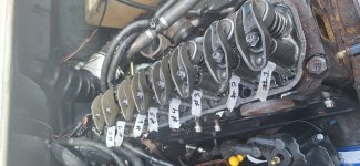
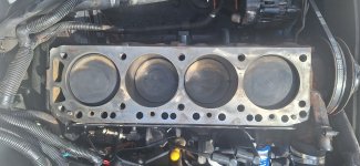
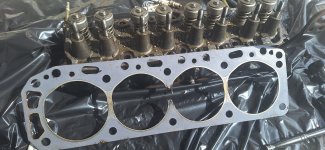
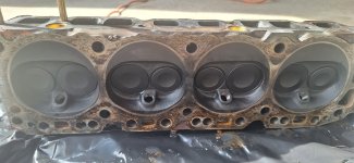
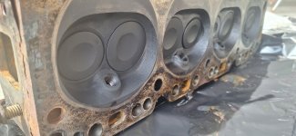
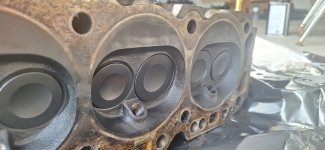
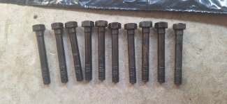
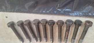
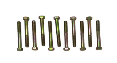
Hey guys, so just finished taking it all apart. Here are some pictures. Thankfully the culprit is the head gasket lol. Also I inserted 2 pictures of the head bolts. Not sure how visible or what sort of inspection they need. I cleaned them up with acetone and they don't seem to have any rust or anything. Just wondering if it's okay if I resue them.
 

Attachments

  • 1000079770.jpg
    1000079770.jpg
    852.7 KB · Views: 7
  • 1000079782.jpg
    1000079782.jpg
    894.1 KB · Views: 8
  • 1000079784.jpg
    1000079784.jpg
    1.1 MB · Views: 8
  • 1000079785.jpg
    1000079785.jpg
    824.6 KB · Views: 7
  • 1000079786.jpg
    1000079786.jpg
    735.1 KB · Views: 6
  • 1000079787.jpg
    1000079787.jpg
    807.5 KB · Views: 6
  • 1000079792.jpg
    1000079792.jpg
    919.4 KB · Views: 6
  • 1000079793.jpg
    1000079793.jpg
    779 KB · Views: 7

Scott06

Admiral
Joined
Apr 20, 2014
Messages
7,193
Hey guys, so just finished taking it all apart. Here are some pictures. Thankfully the culprit is the head gasket lol. Also I inserted 2 pictures of the head bolts. Not sure how visible or what sort of inspection they need. I cleaned them up with acetone and they don't seem to have any rust or anything. Just wondering if it's okay if I resue them.
clean the head bolts and chase threads defintely ok to reuse.

It may be the picture but look at the block closely where the gasket was blown between 2 & 3 - make sure the deck surface is not damaged as it can get fire slotted and cut so the new gasket wont take.

Do you know if it overheated or if timing was to far advanced? Just want o ensure root cause of gasket blow is solved
 

kenny nunez

Captain
Joined
Jun 20, 2017
Messages
3,463
Just to be sure stick a long Phillips screwdriver in each of the head bolt holes. I have have never seen an inline GM block that where the bolt holes were closed. I always used #2 Permatex on the threads.
 

ESGWheel

Master Chief Petty Officer
Joined
Aug 29, 2015
Messages
822
Congrats!!! I love the way you tagged the pushrods ;-)

Regarding the head bolts > there are a lot of opinions out there and ultimately it comes down to ‘are they overstretched’ > a bolt stretches for the clamping force and if it is not ‘overstretched’ it will spring back and can be reused. Suspect yours are not overstretched and thus can reuse as Soctt suggests. However, if the flatness check indicates a greatly out of spec flatness (warped head or block to the point needs to be fixed), then yes, need new head bolts IMO. The key as highlighted before is clean the threads of the bolts (wire brush) and chase (thread chaser) the holes.

Scott also highlighted the possibility of “fire slotting” and that is a significant concern. As the name implies its due to one cylinder combustion gasses passing thru to the other cylinders and this back and forth of a flame between them like a never-ending ping pong game causes the metal of the head and or the block to erode.

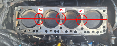
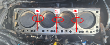
How to know if too much? Clean that block and head as discussed in step 4 of post #29. Then from there use the straight edge across the block and head as discussed in step 5.1 of same post. But also do extra checks of the areas between the cylinders as indicated in the two attachments below. The key is to see for those areas circled what the “flatness” is. Post the numbers as indicated i.e. 1a = xx, 1b = xx, 2a = yy, etc.

And while you are at it also post the overall flatness indicating as best you can what the numbers are and where. I am using Greenshot > a freeware software that is east to use.
 

Attachments

  • Flatness Extra Check 1.png
    Flatness Extra Check 1.png
    819.8 KB · Views: 3
  • Flatness Extra Check 2.png
    Flatness Extra Check 2.png
    862.6 KB · Views: 3

DanOnTheBoat

Seaman Apprentice
Joined
Sep 15, 2024
Messages
48
clean the head bolts and chase threads defintely ok to reuse.

It may be the picture but look at the block closely where the gasket was blown between 2 & 3 - make sure the deck surface is not damaged as it can get fire slotted and cut so the new gasket wont take.

Do you know if it overheated or if timing was to far advanced? Just want o ensure root cause of gasket blow is solved
Perfect thanks!

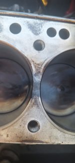
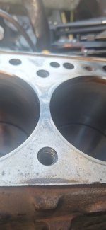
This is what the block looks like in between the two cylinders. Not sure how good you can see it but I'm assuming this is what fire slotted means?
 

Attachments

  • 1000079814.jpg
    1000079814.jpg
    1 MB · Views: 2
  • 1000079813.jpg
    1000079813.jpg
    971.6 KB · Views: 2

DanOnTheBoat

Seaman Apprentice
Joined
Sep 15, 2024
Messages
48
Just to be sure stick a long Phillips screwdriver in each of the head bolt holes. I have have never seen an inline GM block that where the bolt holes were closed. I always used #2 Permatex on the threads.
I actually did that while I was cleaning the bolt threads, but with a tooth pick just so I dont damage anything around... But yeah there is absolutely nothing under the head bolts, it goes straight through to the block cooling system. Which makes me wonder if I should put something on the bolts so water doesnt go up them...
 

DanOnTheBoat

Seaman Apprentice
Joined
Sep 15, 2024
Messages
48
Congrats!!! I love the way you tagged the pushrods ;-)

Regarding the head bolts > there are a lot of opinions out there and ultimately it comes down to ‘are they overstretched’ > a bolt stretches for the clamping force and if it is not ‘overstretched’ it will spring back and can be reused. Suspect yours are not overstretched and thus can reuse as Soctt suggests. However, if the flatness check indicates a greatly out of spec flatness (warped head or block to the point needs to be fixed), then yes, need new head bolts IMO. The key as highlighted before is clean the threads of the bolts (wire brush) and chase (thread chaser) the holes.

Scott also highlighted the possibility of “fire slotting” and that is a significant concern. As the name implies its due to one cylinder combustion gasses passing thru to the other cylinders and this back and forth of a flame between them like a never-ending ping pong game causes the metal of the head and or the block to erode.

How to know if too much? Clean that block and head as discussed in step 4 of post #29. Then from there use the straight edge across the block and head as discussed in step 5.1 of same post. But also do extra checks of the areas between the cylinders as indicated in the two attachments below. The key is to see for those areas circled what the “flatness” is. Post the numbers as indicated i.e. 1a = xx, 1b = xx, 2a = yy, etc.

And while you are at it also post the overall flatness indicating as best you can what the numbers are and where. I am using Greenshot > a freeware software that is east to use.
Lol thanks, tried to be as neat as I could. Labbeled absolutely every sinlge wire.

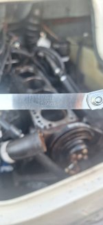
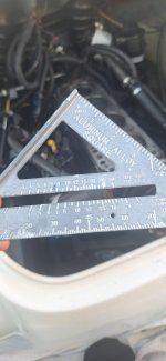
That makes sense thanks a lot. I've cleaned the block with acetone, and scrapped away any debris and wiped the top of block and cylinder walls and pistons with WD40 just so it doesn't rust. I've also checked to see if my block is warped especially where the head gasket blew and I used the lowest feeler guage I had which was 0.04mm(I believe it shouldn't be no more than 0.08mm for my engine) and it didn't go through at any of the spots.

Here is what I used, I know probably not the most accurate, but I will see if they have a straight edge in store and check ones more...
 

Attachments

  • 1000079819.jpg
    1000079819.jpg
    894.4 KB · Views: 2
  • 1000079818.jpg
    1000079818.jpg
    854.1 KB · Views: 2
Top