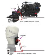
I/O (Sterndrive) Conversion to Outboards

Pmt133

Lieutenant Junior Grade
Joined
Jan 6, 2022
Messages
1,180
Totally ignorant question but would the more rapid cooling be detrimental?
I don't know. I know guys chill poly when doing layups in the heat... I'd imagine it would work fine the other way. Once it kicks... it kicks in my experience with it.
 

tpenfield

Moderator
Staff member
Joined
Jul 18, 2011
Messages
18,666
My preference is to start cold and add heat once the glass is laid up. I’m thinking if the resin were to start warm, it would tend to kick too fast and cooling it down would be too late.

I’m using VE resin, so it’s open time is a bit longer than poly resin.
 

Pmt133

Lieutenant Junior Grade
Joined
Jan 6, 2022
Messages
1,180
Yeah. Even at 1% when I was glassing at 100f that stuff was cured by the second layup (half hour or less). Poly was hell to work with when warm.

You could always bump up the catalyst too. 3% is still acceptable for most resins at the right conditions. Though I understand why you'd want to be closer to 2.
 

tpenfield

Moderator
Staff member
Joined
Jul 18, 2011
Messages
18,666
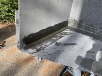
I got out there early this AM to check the glass/resin. It cured OK.

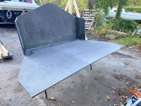
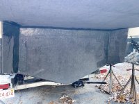
Here is a pic of the 4 pieces of the contact area set in place and glassed at the edges/corners.
IMG_8799.JPG
.
I used some cardboard on the transom as a 'spacer' to mimic the fiberglass thickness, then stuck the Coosa pieces to the cardboard. It seemed to work OK. I figured the cardboard was about 3/32", which would give me about 0.09" thickness offset to account for the glassing on the transom-mating side.

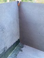
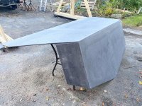
With a couple of swift tugs, the thing came off. Looks OK . . . probably as good as I was going to get.
IMG_8800.JPG
.
IMG_8801B.JPG
.
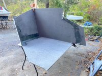
I put the center support in place to see how well it matched the transom angle . . . Looks good!
IMG_8802.JPG
.
No gaps . . .
IMG_8803.JPG
.
IMG_8804.JPG
.
I need to check some dimensions and then start putting the rest of it together. The transom 'plate' and the top plate are going to have some decent-sized cut-outs for fabrication and assembly access. I'm thinking that I won't make the cut-outs until much of the box structure is fastened together.
 
Last edited:

tpenfield

Moderator
Staff member
Joined
Jul 18, 2011
Messages
18,666
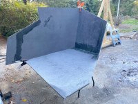
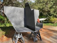
I moved things to a more sunny location in the yard . . . I think the sun will be enough to cure the resin.
IMG_8806.JPG
I installed the main (center) support. This piece I am glassing in - just so it stays put during assembly of all the other pieces.
IMG_8807.jpg
.
IMG_8808.JPG
 

tpenfield

Moderator
Staff member
Joined
Jul 18, 2011
Messages
18,666
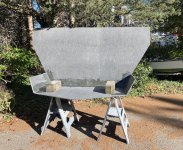
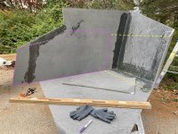
It's a good thing that I was paying attention in Geometry class (way back when) 🤓. Figuring out the shape & dimensions of the outer supports has been a bit challenging, but I think I got it now.:unsure:

IMG_8809.JPG
.
I'll have to make an adjusting cut in the center support to match the outer supports. (I knew it didn't look right . . .) :rolleyes:

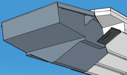
I'm trying to capture this shape (below) for the transition from the planing surface to the outboard transom.
.Screenshot 2025-11-06 at 1.08.14 PM.png
.
Hopefully this will be right . . .:unsure:
 

flashback

Rear Admiral
Joined
Jun 28, 2002
Messages
4,128
All this gets bolted on to an existing transom that to my knowledge was not designed to carry much weight.
 
Top